
Plastic panel, particularly for use as production pallet

a technology of production pallets and plastic panels, which is applied in the direction of manufacturing tools, molding pallets, transportation and packaging, etc., can solve the problems of inconvenient use, increased wear and tear of pallets, and inability to use, etc., and achieve the effect of convenient molding, strengthening, and joining

Active Publication Date: 2008-07-31
STROBL JR FREDERICK P +1
View PDF38 Cites 9 Cited by
  • Summary
  • Abstract
  • Description
  • Claims
  • Application Information

AI Technical Summary

Benefits of technology

[0010]One of the primary objects of the invention is to provide an improved plastic panel which may be, but is not necessarily, used as a production board or pallet for supporting and transporting concrete masonry units during the fabrication of the latter. In particular the invention provides a novel configuration for the separate halves of a plastic panel, which configuration facilitates molding, strengthening, joinder and maintaining the joined halves together to present the complete panel.

Problems solved by technology

In addition, the pallets are subject to additional wear and tear because they must be handled by automated devices such as stackers conveyors and / or by human operated machines such as fork lifts.
In addition it has been known that such products sometimes wear out so as to no longer be useful.
Dimensional stability is highly desirable and yet it is difficult to fabricate a panel from a thermoplastic material without substantial warping and / or difficulty in filling the mold.
Furthermore, where internal steel strengthening bars are utilized to provide strength and rigidity to the plastic panel, the reclamation of the thermoplastic material from worn out panels is hindered.

Method used


Image

  • Plastic panel, particularly for use as production pallet
  • Plastic panel, particularly for use as production pallet
  • Plastic panel, particularly for use as production pallet

Examples


Embodiment Construction

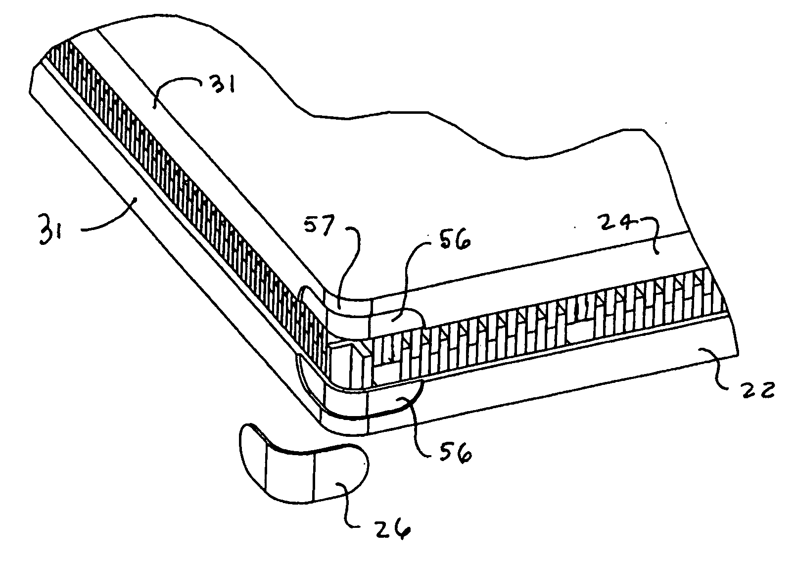
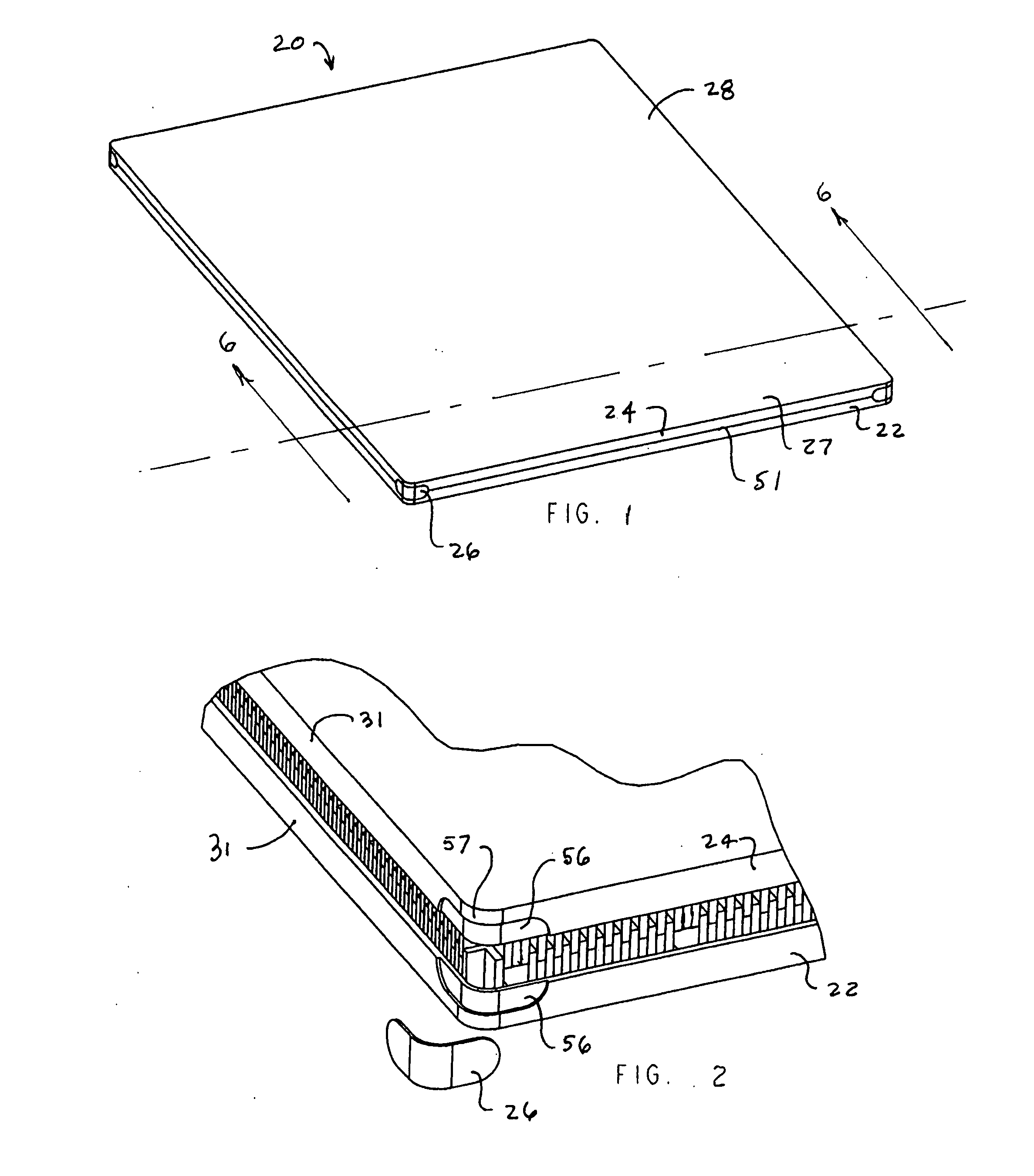
[0033]A preferred embodiment of a plastic panel which embodies the concepts and principles of the invention is illustrated in FIG. 1 where the same is identified broadly by the reference numeral 20. The plastic panel 20 as illustrated in FIG. 1 is in a form having particular utility as a production board or pallet. In particular boards such as the board 20 have particular utility in the production of unitary concrete masonry products such as paving stones and the like. In use, the individual paving units are formed and carried by the board throughout the various unit processes involved in the production of the masonry products including molding, compacting, curing, etc.

[0034]Plastic panels useful as production pallets in the production of masonry products often come in standard sizes well known to those skilled in the art and may preferably be rectangular and may have outer dimensions which may be dependent upon the production facilities and may vary from about 2 ft×3 ft to about 4 ...


PUM


Abstract

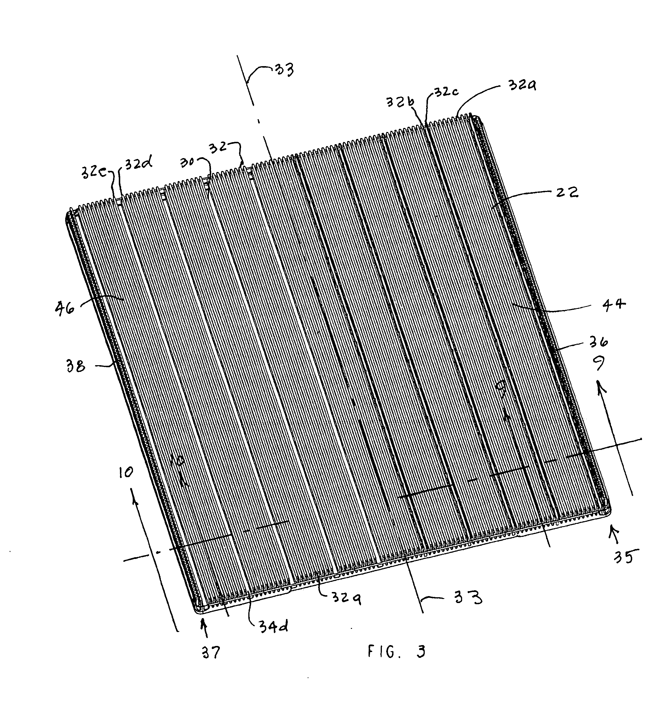
A plastic panel which may be used as a production pallet in the production of unitary concrete masonry products includes first and second joinable portions. The portions each comprise a support backing including an outer surface and an inner face, and a plurality of ribs extending outwardly away from said inner face. The ribs of a first grouping thereof are parallel with one another and extend across a first area of the face in a first direction, and the ribs of a second grouping thereof extend across a second area of the face in a second direction which is not parallel with said first direction. The panel portions are configured, disposed and arranged so as to join with one another in generally overlapping and mated relationship with the outer surfaces disposed in spaced apart opposing relationship, with the first groupings of ribs of the respective portions disposed in intermeshing and mating relationship with each other, and with the second groupings of ribs of the respective portions also disposed in intermeshing and mating relationship with each other whereby to present said plastic panel.

Description

CROSS REFERENCE TO RELATED APPLICATION[0001]NoneBACKGROUND OF THE INVENTION[0002]1. Field of the Invention[0003]The present invention relates to plastic panels (or slabs) and particularly to such items for use as production boards and / or pallets and the like. Even more particularly the invention relates to production boards or pallets useful in the production of unitary concrete masonry products such as paving stones and the like.[0004]2. The Prior Art Background[0005]Concrete masonry units such as paving stones and the like are produced in manufacturing facilities where the paving stones are cast and cured and eventually stored. The production operations include, inter alia, molding, compacting, vibrating, heating in high humidity, washing, brushing, cleaning, stacking, etc. Traditionally the stones are carried on a production pallet during the various production operations. Such pallets are thus exposed to the same set of conditions as the stones undergoing production. In addition...

Claims


Application Information

Patent Timeline
IPC IPC(8): B65D19/38
CPCB28B7/0055B65D19/0012B65D2519/00034B65D2519/00069B65D2519/00273B65D2519/00567B65D2519/00288B65D2519/00318B65D2519/00407B65D2519/00412B65D2519/00278Y10S108/901
Inventor STROBL, FREDERICK P.LEGARE, BRADLEY D.
Owner STROBL JR FREDERICK P
Learn More