
Disk Replacement Endoprosthesis

a technology of endoprosthesis and disc, which is applied in the field of biomechanical structure, can solve the problems of serious neurological dysfunction, arm pain, and non-surgical treatment of pain, and achieve the effects of reducing the risk of stroke, and improving the effect of the patient's overall health

Inactive Publication Date: 2008-07-24
KYPHON
View PDF10 Cites 32 Cited by
  • Summary
  • Abstract
  • Description
  • Claims
  • Application Information

AI Technical Summary

Problems solved by technology

However, in some cases, these non-surgical treatments do not relieve the pain.
One cause of pain can be herniation of a cervical disk in which a rupture or bulge in the cervical disk compresses on nerve roots of the spinal cord.
In addition to neck pain, the nerve compression can cause arm pain and serious neurological dysfunction.
In cervical vertebrae, stenosis results in a reduction foraminal area (i.e., the available space for the passage of nerves and blood vessels) which compresses the cervical nerve roots and causes radicular pain.
Another symptom of cervical spinal stenosis is myelopathy, which results in neck pain and muscle weakness.
Extension and ipsilateral rotation of the neck further reduces the foraminal area and contributes to pain, nerve root compression, and neural injury.
Cervical discectomy and fusion suffers from the disadvantage that fusion of the two adjacent cervical vertebrae leads to a reduction in normal range of motion and increases the amount of stress or wear on the vertebrae adjacent the fusion.
The donor site for the bone graft is a significant source of postoperative pain and other complications.
Cervical disk arthroplasty is a difficult and technically challenging invasive surgical procedure.

Method used


Image

  • Disk Replacement Endoprosthesis
  • Disk Replacement Endoprosthesis
  • Disk Replacement Endoprosthesis

Examples


Embodiment Construction

[0030]In view of the foregoing background of the invention, it is an object of the present invention to provide a minimally-invasive disk replacement endoprosthesis that maintains motion and balance while providing decompression and alleviating pain caused by disc herniation, stenosis, and other such conditions caused by damage to, or degeneration of, the cervical spine.

[0031]It is also an object of this invention to provide a disk replacement endoprosthesis that is simpler to implant and thus less likely to necessitate reversion to a fusion procedure.

[0032]It is a further object of the present invention to provide minimally-invasive procedures for disk replacement arthroplasty that are less invasive than current technologies and have improved results.

[0033]In accordance with the objects and background of the invention, embodiments of the present invention provide for a minimally-invasive surgical implantation method and endoprosthesis for total disk arthroplasty that alleviates pai...


PUM

PropertyMeasurementUnit
angleaaaaaaaaaa
angleaaaaaaaaaa
angleaaaaaaaaaa

Abstract

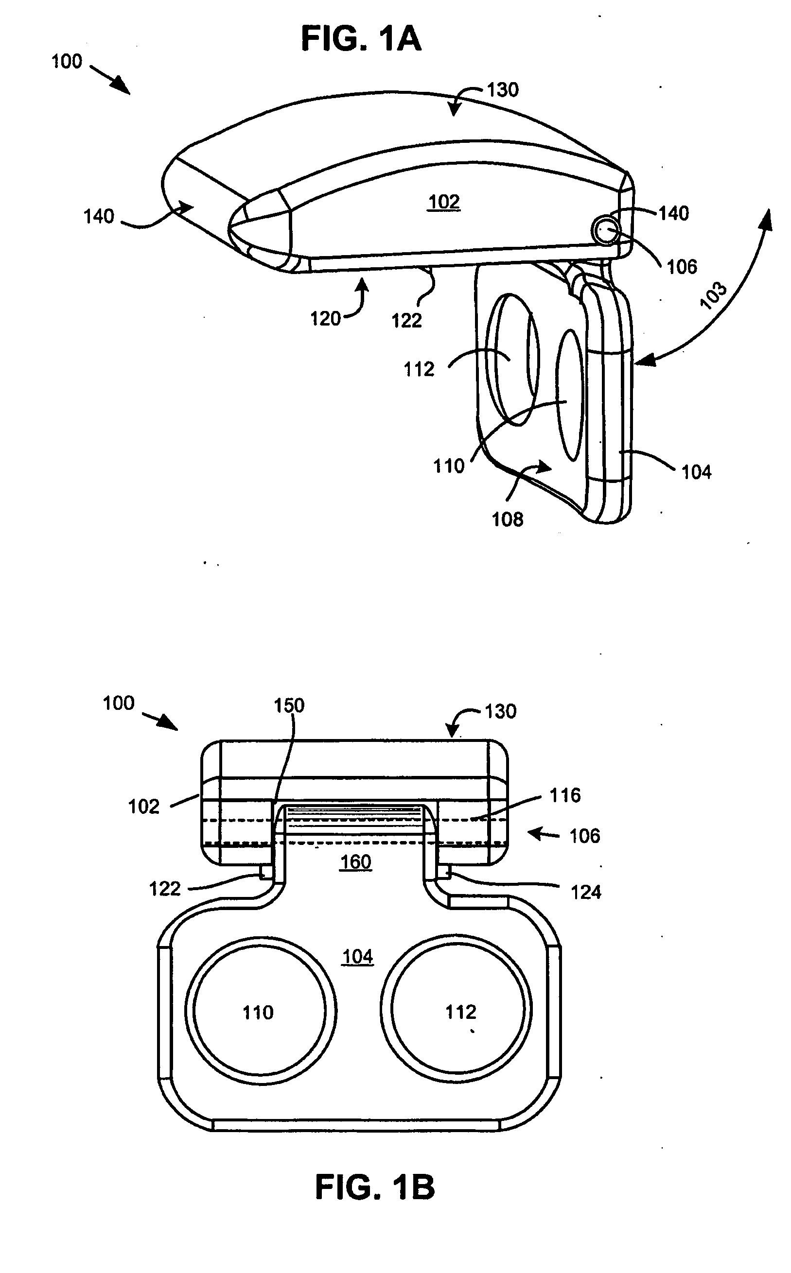
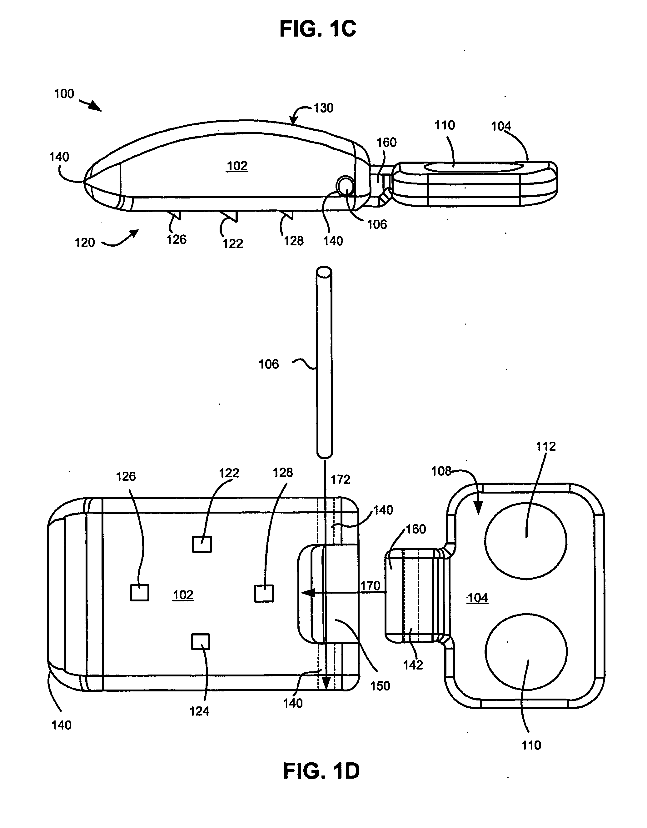
A disk replacement endoprosthesis and a procedure for implantation of the endoprosthesis to treat pain, nerve root compression, and neural injury caused by degeneration or injury to vertebral disks. The endoprosthesis may include an intervertebral wedge or other body having a lead-in distractor. A fastening plate may be attached to the intervertebral wedge by a joint such that the first fastening plate may move from a first configuration in which the first fastening plate is in-line with the intervertebral wedge to facilitate insertion of the endoprosthesis to a second configuration in which the first fastening plate is in contact with an anterior surface of the inferior vertebral body for attachment thereto.

Description

CROSS-REFERENCES TO RELATED APPLICATIONS[0001]This U.S. Provisional Patent application claims the benefit of under 35 U.S.C. §109(e) of U.S. Provisional Patent Application No. 60 / 853,955, as filed on Oct. 24, 2006, the disclosure of which is incorporated by reference.STATEMENT AS TO RIGHTS TO INVENTIONS MADE UNDER FEDERALLY SPONSORED RESEARCH AND DEVELOPMENT[0002]NOT APPLICABLEREFERENCE TO A “SEQUENCE LISTING,” A TABLE, OR A COMPUTER PROGRAM LISTING APPENDIX SUBMITTED ON A COMPACT DISK[0003]NOT APPLICABLEBACKGROUND OF THE INVENTION[0004]The spinal column is a bio-mechanical structure composed primarily of ligaments, muscles, vertebrae and intervertebral disks. The bio-mechanical functions of the spine include: (1) support of the body, which involves the transfer of the weight and the bending movements of the head, trunk and arms to the pelvis and legs, (2) complex physiological motion between these parts, and (3) protection of the spinal cord and the nerve roots.[0005]Neck pain affe...

Claims


Application Information

Patent Timeline
Patent Type & Authority Applications(United States)
IPC IPC(8): A61F2/44
CPCA61F2/442A61F2/4425A61F2002/30471A61F2002/30538A61F2002/30578A61F2310/00976A61F2002/30769A61F2002/30904A61F2220/0091A61F2250/0006A61F2310/00023A61F2002/30624
Inventor MITCHELL, STEVEN T.YERBY, SCOTT A.
Owner KYPHON
Learn More