
Method and apparatus for repairing turbine components

a technology for turbine components and parts, applied in the direction of soldering apparatus, manufacturing tools, instruments, etc., can solve the problems of turbine components themselves becoming twisted, distorted, twisted and bent, and material at the outer tips, edges or surfaces of turbine components worn away and damaged,

Active Publication Date: 2008-07-24
OPTOMEC INC
View PDF4 Cites 33 Cited by
  • Summary
  • Abstract
  • Description
  • Claims
  • Application Information

AI Technical Summary

Problems solved by technology

During use, the material at the outer tips, edges or surfaces of turbine components is worn away and damaged, and, in addition, these turbine components tend to become distorted, twisted and bent during use, caused in part by the high temperatures and the temperature variations to which the turbine components are exposed.
However, because of the aforesaid distortion of the turbine components, the turbine components themselves become twisted and bent, and the uniformity of the turbine components in their original condition is lost.
Accordingly, because of these distortions, and the variations in the distortions, it is difficult to repair turbine components by welding new material at the outer tips, edges or surfaces of the turbine components.
This manual operation is obviously a slow and labor-intensive operation, and in many cases the quality of the weld is poor, and in some cases must be reworked completely.
However, these systems are cumbersome to change part-holding fixtures from one machine to another to retained referenced datum, and they are quite slow in most cases.
Also, some machines use a system by which video or photographic two-dimensional images are taken within the machine to reverse engineer the turbine component, but these machines are limited to obtaining two-dimensional images at different views, and multiple 2D views can not faithfully reverse engineer some turbine component surfaces which are obviously three-dimensional.

Method used


Image

  • Method and apparatus for repairing turbine components
  • Method and apparatus for repairing turbine components
  • Method and apparatus for repairing turbine components

Examples


Embodiment Construction

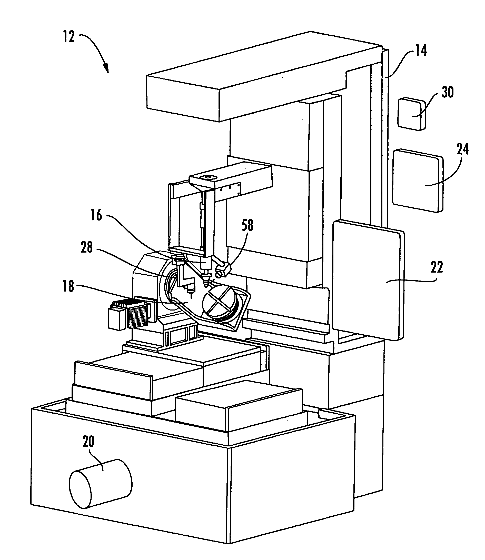
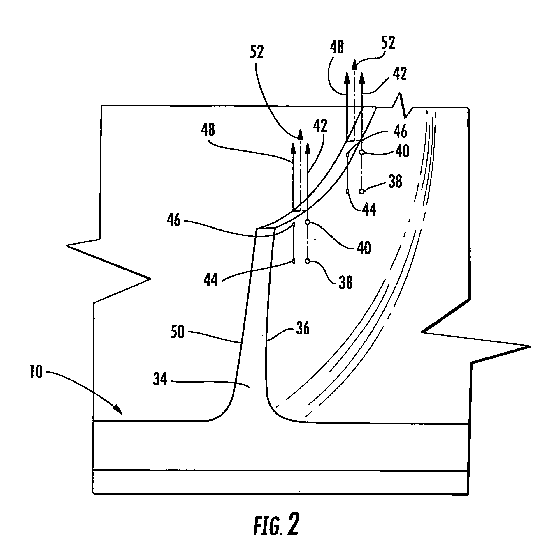
[0018]Generally, the present invention includes an apparatus and method by which the three-dimensional form or configuration of a distorted workpiece, such as a turbine component, is reverse engineered, and then this reverse engineering capability is combined with welding equipment, preferably a laser powder fusion welder, all integrally carried within a single machine, whereby a tool path unique to each workpiece is created and the welding machine accurately replaces lost material on the workpiece. The present invention consists of a series of operations or steps, preferably carried out by a single machine, which are described in greater detail below.

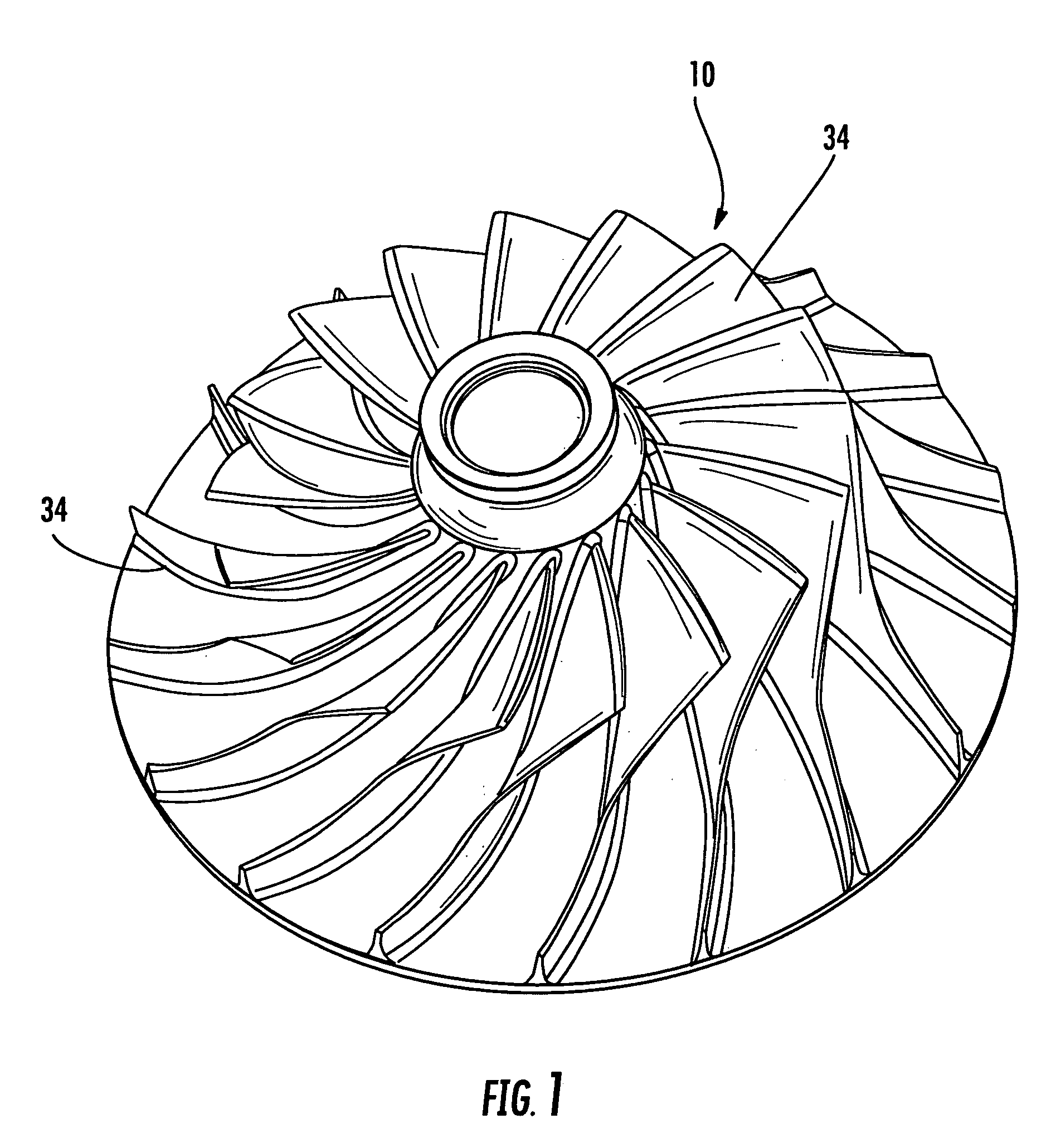
[0019]FIG. 1 illustrates a turbine wheel or impeller 10, which is a typical turbine component to which the method and apparatus of the present invention is applicable, but it will be understood that the present invention can be used with a variety of other workpieces and turbine components, such as vanes, shrouds, seals and duct segmen...


PUM

PropertyMeasurementUnit
shapeaaaaaaaaaa
temperaturesaaaaaaaaaa
temperatureaaaaaaaaaa

Abstract

The present invention includes an apparatus and method by which the three-dimensional form or configuration of a distorted workpiece, such as a turbine component, is reverse engineered, and then this reverse engineering capability is combined with welding equipment, preferably a laser powder fusion welder, all integrally carried within a single machine, whereby a tool path unique to each workpiece is created and the welding machine accurately replaces lost material on the workpiece. The present invention consists of a series of operations or steps, preferably carried out by a single machine.

Description

CROSS-REFERENCE TO RELATED APPLICATIONS [0001]This application is entitled to the benefit of, and claims priority to, provisional U.S. Patent Application Ser. No. 60 / 881,359, filed Jan. 19, 2007, and entitled “METHOD AND APPARATUS FOR REPAIRING TURBINE PARTS,” the entirety of which is incorporated herein by reference.BACKGROUND OF THE PRESENT INVENTION [0002]The present invention relates generally to a method and apparatus for repairing a workpiece, such as turbine components and the like.[0003]As used herein, the term “turbine components” is intended to include individual turbine blades, blades mounted on a disk, blades that are machined integral to a rotor or to an impeller (e.g. Blisks), air foils, vanes and shrouds.[0004]During use, the material at the outer tips, edges or surfaces of turbine components is worn away and damaged, and, in addition, these turbine components tend to become distorted, twisted and bent during use, caused in part by the high temperatures and the temper...

Claims


Application Information

Patent Timeline
Patent Type & Authority Applications(United States)
IPC IPC(8): B23K9/095B23P6/00
CPCB22F2998/00B23P6/007F01D5/005Y10T29/49318B23K35/0244B23K26/345B22F3/1055B22F3/003B23K26/342Y02P10/25B22F10/25
Inventor DRECHSLER, DAVID E.COBB, JAMES N.HUMBER, J. MICHAEL
Owner OPTOMEC INC
Learn More