
Shielded flat pair cable with integrated resonant filter compensation

a flat pair cable and filter compensation technology, applied in the field of shielded flat pair cables with integrated resonant filter compensation, can solve the problems of insufficient interest from organizations that develop performance, lack of transformation or advancement in structure and assembly architecture, and large volume of cables used for conveying electricity from generating stations to load sites, etc., to reduce signal loss, eliminate intra-pair skew, and recover signal energy

Inactive Publication Date: 2008-07-24
NAIR RAJENDRAN
View PDF21 Cites 12 Cited by
  • Summary
  • Abstract
  • Description
  • Claims
  • Application Information

AI Technical Summary

Benefits of technology

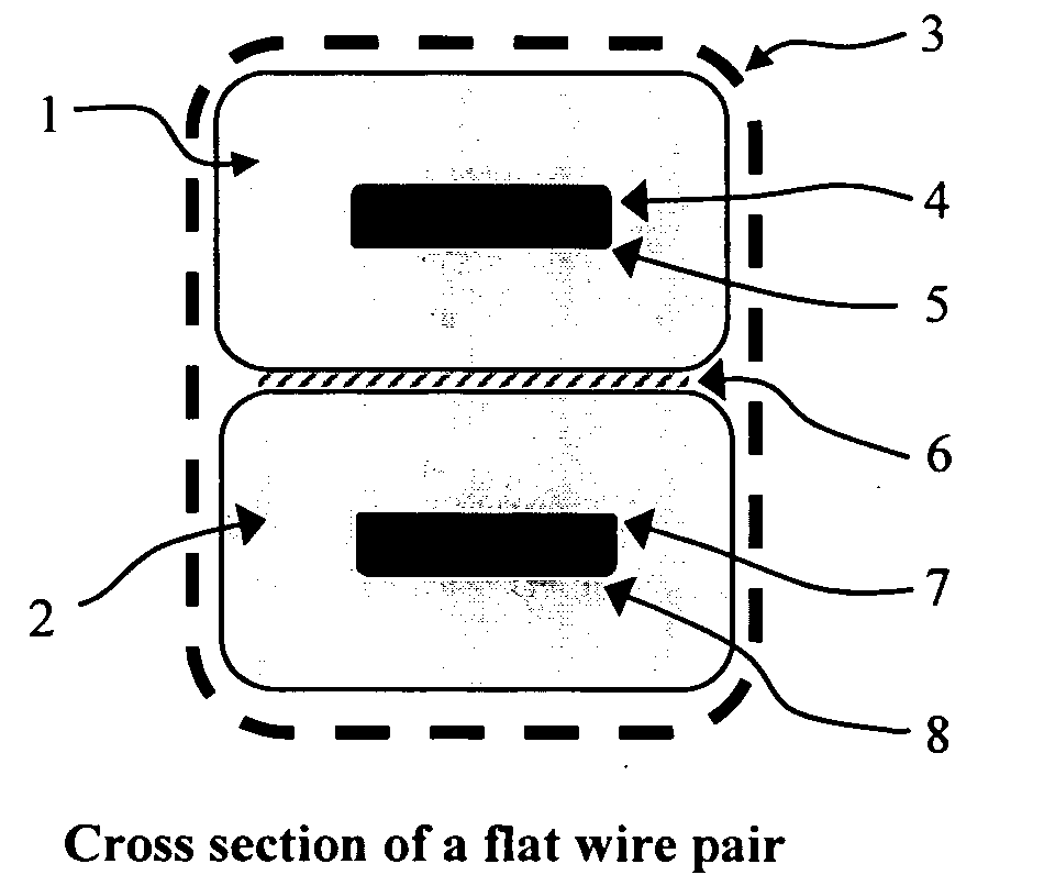
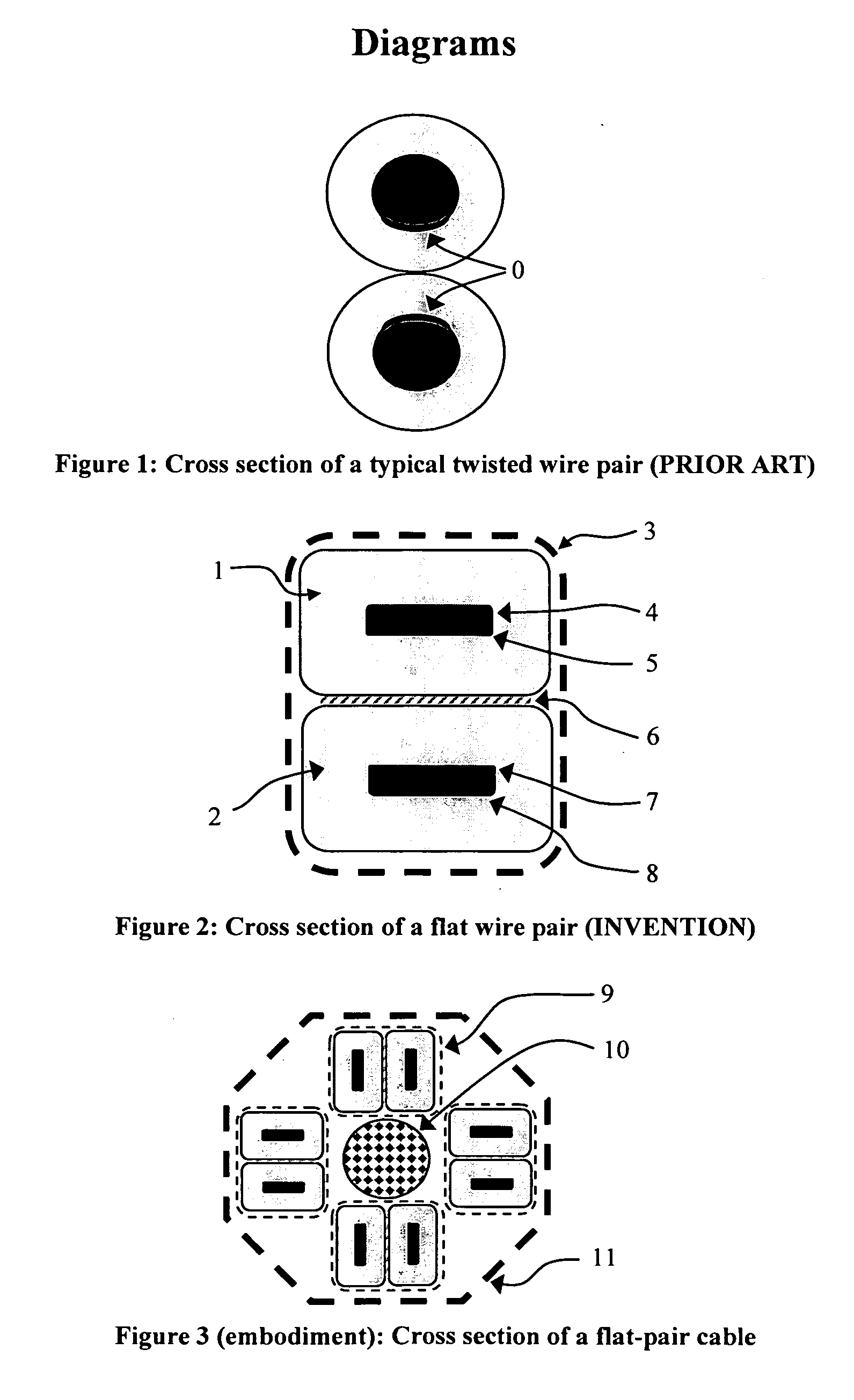
[0012]The invention implements flattened conducting wires coated with insulation that are bonded to each other, providing approximately rectangular cross-sections and flat surfaces for the transport of charge through the wires. The flat wire pair may then be twisted for additional cross-talk minimization, with the twist occurring simultaneously and in identical fashion on both wires due to their attached arrangement. The terminating ends of the cable are routed on an insulating substrate forming a connector body, with the traces ending in conducting structures providing a matched resonating filter function. This filter is tuned to provide maximal benefit for the highest significant spectral content in transmitted signals. Through these enhancements, the invention cable architecture substantially reduces signal loss due to skin-effect and eliminates intra-pair skew. Through its active interconnect design, it amplifies high-frequency content and recovers signal energy lost due to attenuation through the length of the cable and connector termination.

Problems solved by technology

Cables employed for conveying electricity from generating stations to load sites are large and heavy, and therefore supported on tall poles constructed of insulating material anchored firmly to the ground.
In part due to the standardization of cables that defined them in a fashion optimal for the targeted requirement and in large part due to explosive growth in the proliferation and use of computers, these cables are very cost-effective, and have seen very little transformation or advancement in their structure and assembly architecture.
This is in part due to insufficient interest from organizations that develop performance standards in this area, lower volumes of sale as well as the vested interests of industry cliques that develop proprietary specifications for such electronics supporting the business directions they chose.
From a technology perspective, interconnect has largely been considered a passive element in any system, providing sufficient but non-ideal connectivity between different parts of the system.
In that manner, a prior art twisted wire pair, whose cross-section is illustrated in FIG. 1, provides good connectivity for signals flowing in the wires, but is prone to energy loss that is proportional to the data rate, or the frequency of the transmitted signals.
Since conductor surfaces are very uneven, the restriction of current flow to a small volume of conducting material very close to the conductor surface leads to a very significant increase in effective series resistance in the current path, leading to substantial signal attenuation.
This effect manifests both as a limited bandwidth for TWP cables as well as differentiated velocities for the varied spectral content of high-speed binary signals, leading to dispersion.
Additionally, parasitic capacitance at the end of the cables, principally in the connector structures, further attenuates the high-frequency spectral content in the signals.

Method used


Image

  • Shielded flat pair cable with integrated resonant filter compensation
  • Shielded flat pair cable with integrated resonant filter compensation
  • Shielded flat pair cable with integrated resonant filter compensation

Examples


Embodiment Construction

[0020]A prior art twisted wire pair (TWP) cross-section is illustrated in FIG. 1. Key aspects of the design of such a transmission line pair include a fixed separation between the central axes of the two conducting wires, the diameter of the wires and the thickness as well as dielectric permittivity of the insulation coating both wires. The electric field between the two wires passes through the insulation between the wires as well as air space adjacent to them, given the circular nature of the cross section of the wires. The dimensions of the wires, their separation and the nature of the insulating material in between provide a value of inductance and capacitance per unit length that determine the characteristic impedance of the transmission line as the square-root of the ratio of the inductance to the capacitance.

[0021]A principal aspect of TWP's is the twist introduced into the wire pair along its length. This twist entwines both wires with each other and has significant advantag...


PUM


Abstract

A novel flat-wire-pair cable and resonant filter termination employing active interconnect principles is disclosed. The invention implements flattened conducting wires coated with insulation that are bonded to each other, providing approximately rectangular cross-sections and flat surfaces for the transport of charge through the wires. The flat wire pair may then be twisted for additional cross-talk minimization, with the twist occurring simultaneously and in identical fashion on both wires due to their attached arrangement. The terminating ends of the cable are routed on an insulating substrate forming a connector body, with the traces ending in conducting structures providing a matched resonating filter function. This filter is tuned to provide maximal benefit for the highest significant spectral content in transmitted signals. Through these enhancements, the invention interconnect architecture substantially reduces signal loss due to skin-effect and eliminates intra-pair skew. Through its active interconnect design, it amplifies high-frequency content and recovers signal energy lost due to attenuation through the length of the cable and connector termination.

Description

RELATED DOCUMENTS[0001]1. Technical Field of the Invention[0002]Embodiments of the invention relate to electronic wiring and cabling employed to conduct signals from point to point. Such embodiments fall under the category of wired interconnect components.[0003]2. Background & Prior Art[0004]Cables have been in use for transport of electric charge from the early days of the discovery of electricity. Cables employed for conveying electricity from generating stations to load sites are large and heavy, and therefore supported on tall poles constructed of insulating material anchored firmly to the ground. These cables came in pairs (phase, neutral) or combinations of 3 or 4 wires (3-phase with or without a neutral wire) and constituted power transmission lines. In the present day, cables are employed for various purposes including transmission of information in electric or optic form. Cables used for transmission of information in electric form usually consist of a pair of wires which t...

Claims


Application Information

Patent Timeline
IPC IPC(8): H01B11/02H01B7/00
CPCH01B7/0876
Inventor NAIR, RAJENDRAN
Owner NAIR RAJENDRAN
Learn More