
Laser processing apparatus

a technology of laser processing and processing equipment, which is applied in the direction of optical elements, manufacturing tools, instruments, etc., can solve the problems of increasing the size of the laser processing equipmen

Inactive Publication Date: 2008-07-17
SUMITOMO ELECTRIC IND LTD
View PDF22 Cites 32 Cited by
  • Summary
  • Abstract
  • Description
  • Claims
  • Application Information

AI Technical Summary

Benefits of technology

[0008]In order to overcome the above-mentioned problems, it is an object of the present invention to provide a laser processing apparatus which can be miniaturized and which has a structure that serves to provide effective protection of the fiber laser light source.
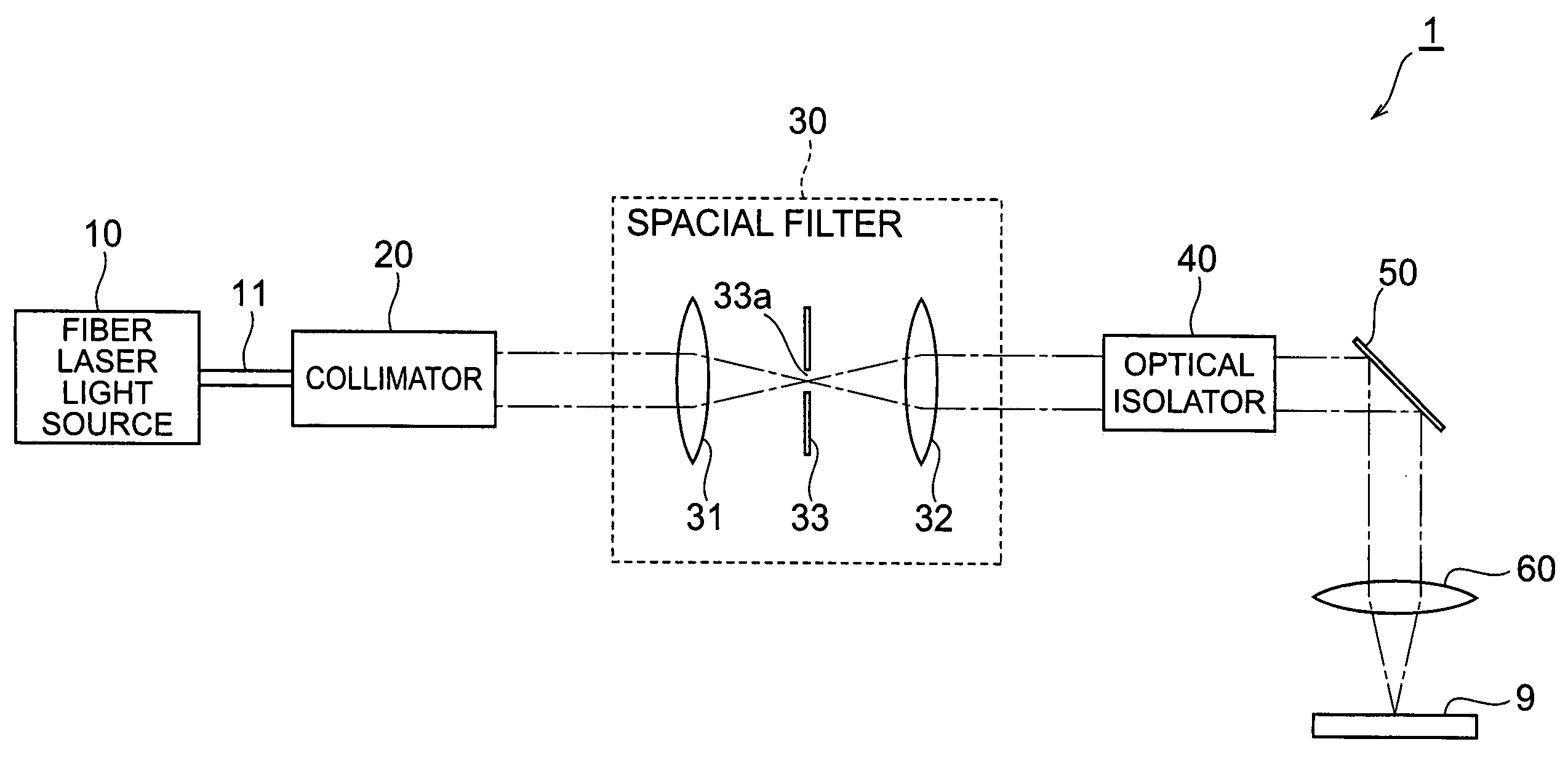
[0011]In the laser processing apparatus according to the present invention, the laser light emitted from the fiber laser light source is collimated by the collimator in a state where the laser light is enlarged to a predetermined beam diameter. The laser light emitted from the collimator is condensed by the first condenser lens after passing through the spatial filter and optical isolator along the forward light path (a light path for laser light that propagates via the collimator, optical isolator, and first condenser lens in that order). When the laser light thus condensed is irradiated onto the object, reflected light (return light) is produced by the object. The return light is collimated by the first condenser lens and then reaches the spatial filter from the optical isolator along the reverse light path (a light path for return light that propagates via the first condenser lens, optical isolator, and collimator in that order) that differs from the forward light path. Hence, at least a part of the return light that is introduced at a predetermined angle to the spatial filter is blocked by the pinhole mask. As a result of this constitution, the return light reaching the fiber laser light source from the optical isolator through the collimator is drastically reduced.
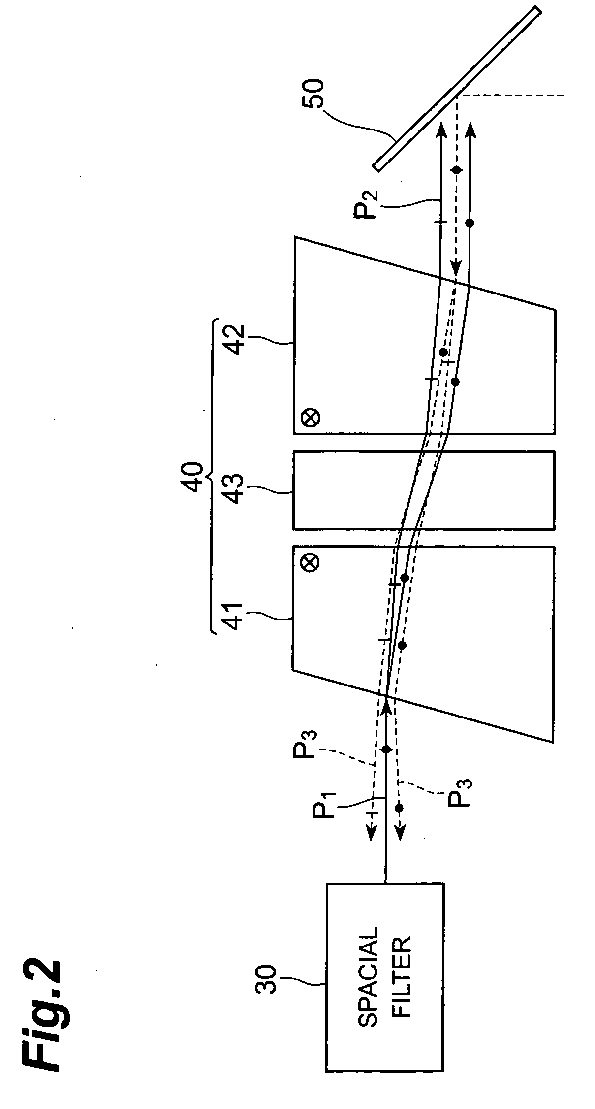
[0013]Furthermore, in the case of an optical isolator including one pair of wedge-shaped birefringence plates and a Faraday rotator, not only is the emitted light from the optical isolator displaced from the original position (light path) but the angle thereof is also shifted. Hence, the focal point of the condenser lens utilized for the spatial filter is further displaced as a result of angular displacement also being applied, and is easily blocked at the periphery of the pinhole of the pinhole mask. The coupling efficiency of the condenser lens is more greatly influenced by the angular displacement than by the positional displacement of the incident beam. This effect is even greater for a spatial filter that uses two condenser lenses.
[0015]That is, the return light propagating in a reverse direction along the forward light path of the laser light from the collimator toward the optical isolator is blocked beforehand by a beam expander disposed between the optical isolator and first condenser lens. Furthermore, the optical isolator itself emits the return light, which propagates in the reverse direction along the forward light path of the laser light from the optical isolator to the first condenser lens, at a predetermined angle with regard to the direction of incidence of the return light. As a result of this constitution, the return light reaching the fiber laser light source from the optical isolator through the collimator is reduced to a large extent.

Problems solved by technology

The inventors have studied conventional laser processing apparatuses in detail, and as a result, have found problems as follows.
As a result, the laser processing apparatus grows in size.

Method used


Image

  • Laser processing apparatus
  • Laser processing apparatus
  • Laser processing apparatus

Examples


first embodiment

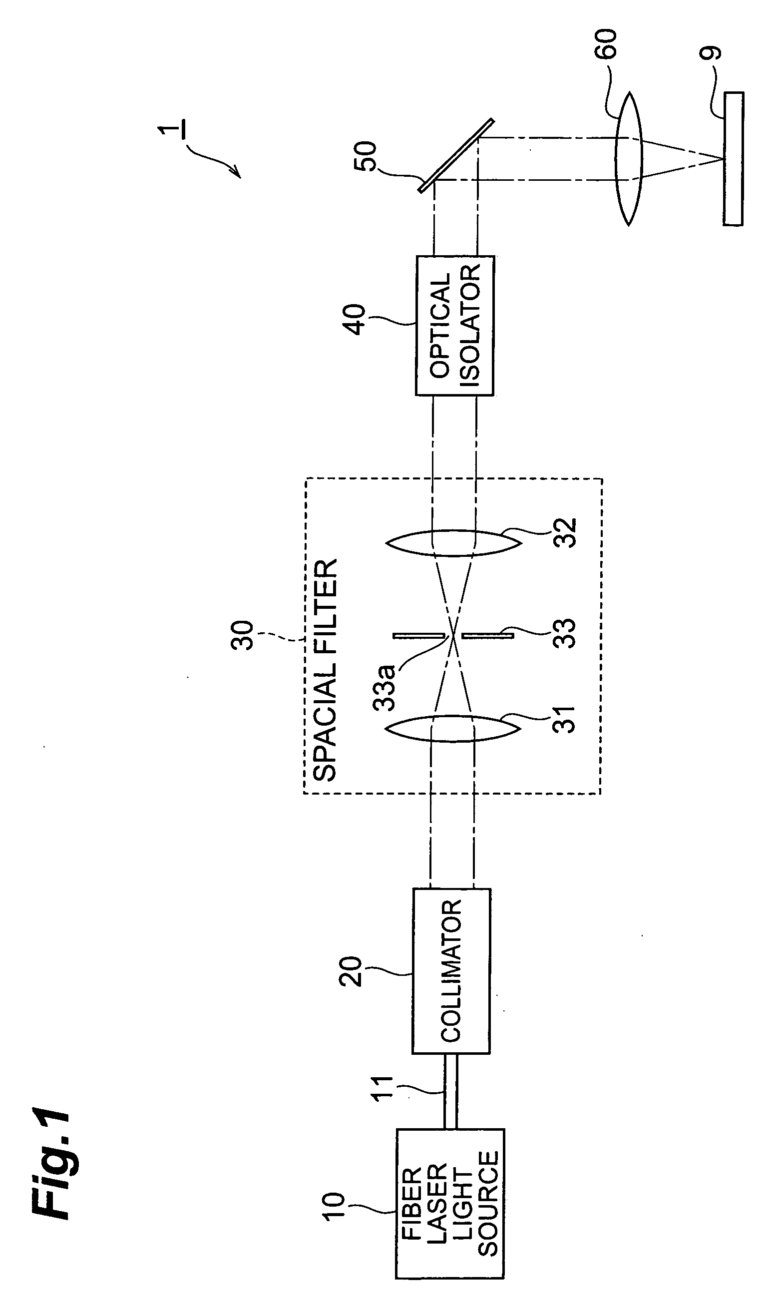
[0027]FIG. 1 is a view showing the constitution of the first embodiment of the laser processing apparatus according to the present invention. As shown in FIG. 1, the laser processing apparatus 1 according to the first embodiment is an apparatus that processes an object 9 (object to be processed) by irradiating laser light condensed with respect to the object 9, and comprises a fiber laser light source 10, a collimator 20, a spatial filter 30, an optical isolator 40, a mirror 50, and a condenser lens 60 (first condenser lens).

[0028]The fiber laser light source 10 includes an amplification optical fiber (a silica-based optical fiber whose core region is doped with the element Yb, for example) as an optical amplification medium and, by supplying pumping light to the amplifying optical fiber, laser light is generated in the amplification optical fiber. The laser light generated in the amplification optical fiber propagates through the optical fiber 11 toward the collimator 20. The optic...

second embodiment

[0043]In the laser processing apparatus 1 according to the first embodiment, the optical isolator 40 emits reflected light (return light), having propagated in the reverse direction along the light path P2 for laser light from the optical isolator 40 to the condenser lens 60, at a predetermined angle to the direction of incidence of the reflected light. The spatial filter 30 is thus effective in the blocking of reflected light propagating along the reverse light path P3 which differs from the forward light path P1. This is because, as shown in FIG. 4A, the total emission angle of the optical isolator 40 which has an opening with a diameter on the order of 3 mm is approximately on the order of one to two degrees to the light that is introduced vertically. However, as shown in FIG. 4B, there are components propagating in the reverse direction along the forward light path P1, within the reflected light components introduced to the optical isolator 40 at an angle of approximately 0.5 de...

third embodiment

[0057]In addition, the third embodiment of the laser processing apparatus according to the present invention possesses the characteristics of both of the first and second embodiments. That is, FIG. 7 shows the constitution of the third embodiment of the laser processing apparatus according to the present invention.

[0058]As shown in FIG. 7, a laser processing apparatus 3 according to the third embodiment is an apparatus that processes the object 9 by irradiating the object 9 with condensed laser light, and comprises a fiber laser light source 10, a collimator 20, a spatial filter 30, an optical isolator 40, a beam expander 70, a mirror 50, and a condenser lens 60 (first condenser lens).

[0059]The fiber laser light source 10 includes an amplification optical fiber (a silica-based optical fiber whose core region is doped with the element Yb, for example) as an optical amplification medium and, by supplying pumping light to the amplification optical fiber, laser light is generated in the...


PUM

PropertyMeasurementUnit
Angleaaaaaaaaaa
Diameteraaaaaaaaaa
Birefringenceaaaaaaaaaa

Abstract

The present invention relates to a laser processing apparatus which can be miniaturized and has a structure for achieving effective protection of the fiber laser light source. The laser processing apparatus comprises a fiber laser light source, a collimator, a spatial filter, an optical isolator, and a condenser lens. The optical isolator emits laser light from the collimator laser light in parallel to the direction of incidence of the laser light, and emits return light from the condenser lens at a predetermined angle with regard to the direction of incidence of the return light. The spatial filter comprises a pair of condenser lenses disposed such that the focal point is formed therebetween, and a pinhole mask disposed such that the pinhole is located at the focal point. At least, a part of the return light emitted from the optical isolator is blocked by the pinhole mask of the spatial filter.

Description

BACKGROUND OF THE INVENTION[0001]1. Field of the Invention[0002]The present invention relates to a laser processing apparatus including a fiber laser light source.[0003]2. Related Background Art[0004]A laser processing apparatus is an apparatus that processes an object to be processed by irradiating the object with laser light. Further, as an example of a laser processing apparatus, an apparatus that comprises a fiber laser light source is known. In a laser processing apparatus comprising a fiber laser light source of this kind, the laser light emitted from the fiber laser light source has a predetermined divergence angle and the laser light is therefore temporarily collimated by a collimator with the beam diameter in an enlarged state. The laser light having been collimated in this manner is condensed on the object by the condenser lens (laser light irradiation).[0005]In addition, an optical isolator is disposed on the light path between the collimator and condenser lens. The optic...

Claims


Application Information

Patent Timeline
IPC IPC(8): G02B27/09G02B27/30G02B27/28B23K26/04
CPCB23K26/0656G02B27/0988G02B27/0927B23K26/066
Inventor NAKAMAE, KAZUOMORIWAKI, HIROKI
Owner SUMITOMO ELECTRIC IND LTD
Learn More