
Image recording apparatus

a technology of image recording and recording apparatus, which is applied in the field of image recording apparatus, can solve problems such as density non-uniformity, and achieve the effect of reducing density non-uniformity and reducing density non-uniformity

Inactive Publication Date: 2005-06-30
KONICA MINOLTA MEDICAL & GRAPHICS INC +1
View PDF9 Cites 2 Cited by
  • Summary
  • Abstract
  • Description
  • Claims
  • Application Information

AI Technical Summary

Benefits of technology

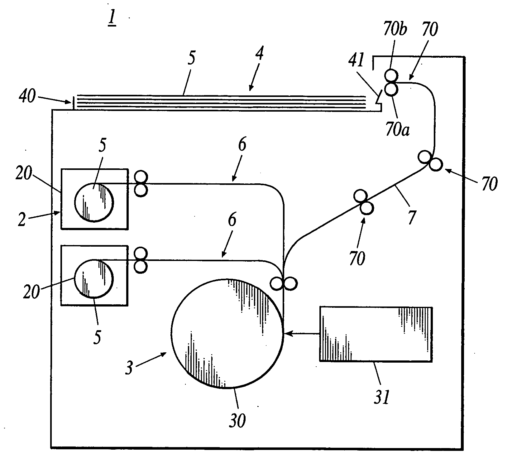
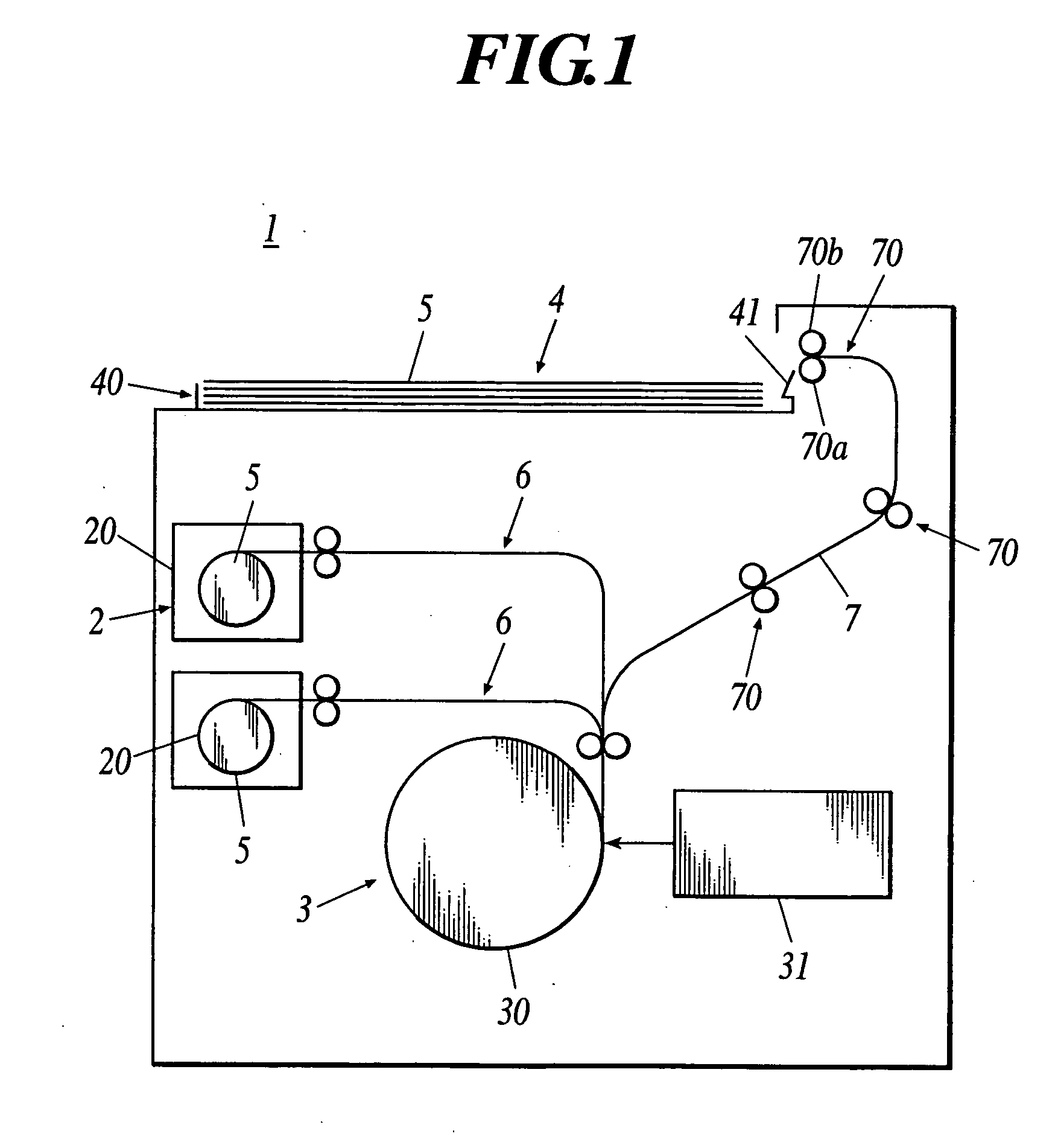
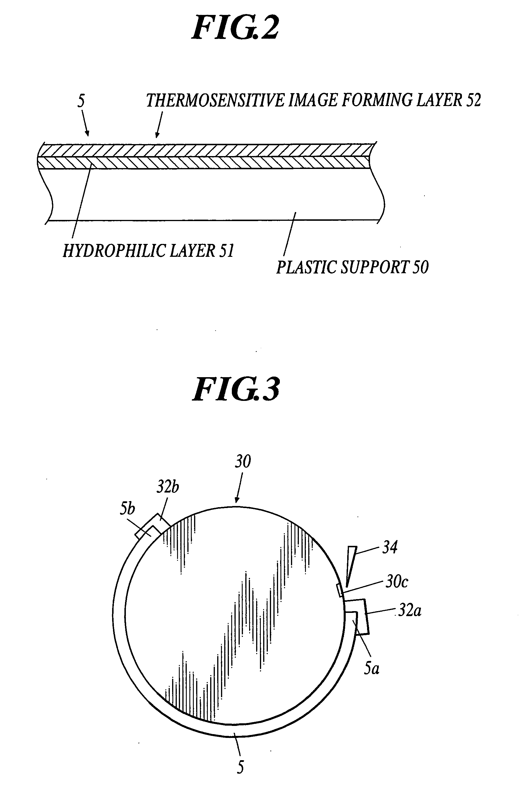
[0012] By forming at least a hydrophilic layer and a thermosensitive layer on a plastic support having optical transparency for infrared light and making surface reflectance of the drum at a wavelenght of light to be used be 0.1 to 10%, the reflectance on the surface of the drum is reduced. Thus, the first problem that light which has not been converted to heat at a thermosensitive image forming layer is transmitted through the plastic support and is reflected on the surface of the drum to react at the thermosensitive image forming layer again, so that the image density increases more than necessary, is solved so that density nonuniformity can be reduced.
[0028] By lowering the image intensity such like 100 to 400 mJ / cm2, the transmitted and return light thereof decreases and density nonuniformity can be reduced under certain condition of the sheet printing plate material and drum. Thus, the first problem is solved and the density nonuniformity can be reduced.

Problems solved by technology

There are following problems in performing scanning exposure of an image data with a light source using the sheet printing plate material or printing plate having a plastic support so that an image is recorded.
Secondly, when some concavoconvex such as clamp groove, suction groove and peel groove is formed on a surface of the drum of the image recording apparatus, density nonuniformity occurs since the distance between the bottom of the groove and the plastic support is different from the distance between the surface of the drum and the plastic support and a reaction on the thermosensitive image forming layer varies.

Method used


Image

  • Image recording apparatus
  • Image recording apparatus
  • Image recording apparatus

Examples


embodiment

[0219] Hereinafter, the invention is specifically explained with the embodiment.

[0220] Reflectances (%) of drums a, b, c and d where surface treatments were different from one another were measured at various wavelength of the light source.

[0221] The reflectance (%) on the surfaces of each drum was merely changed at wavelength of the light source of approximately 660 nm or less. However it increased from approximately 660 nm to 700 nm or more.

[0222]“OLYMPUS USPM” was used as a measuring apparatus. As shown in FIG. 8, “OLYMPUS USPM” irradiates irradiating light to a sample through an objective lens, excludes the reflected light at backside of the sample, leads the reflected light at the sample surface to an aperture of a sensor so as to perform measurement.

[0223] In order to exclude the reflection light from the backside of the sample, the illumination is torus (doughnut shape).

[0224] In the present embodiment, sheet printing plate materials A and B and drums a, b, c and d shown...


PUM

PropertyMeasurementUnit
surface reflectanceaaaaaaaaaa
transmittanceaaaaaaaaaa
thicknessaaaaaaaaaa

Abstract

A sheet printing plate material includes a plastic support having optical transparency for infrared light, and at least a hydrophilic layer and a thermosensitive image formed layer formed on the plastic support, wherein the sheet printing plate material is wound on a drum having surface reflectance of 0.1 to 10% at a wavelength to be used, and the sheet printing plate material is used for a image recording apparatus where the drum is rotated to expose an image data with a light source so that an image is recorded.

Description

BACKGROUND OF THE INVENTION [0001] 1. Field of the Invention [0002] The present invention relates to an image recording apparatus for performing a scanning exposure of an image to the sheet printing plate material and the printing plate of plastic support. [0003] 2. Description of the Related Art [0004] In earlier development, an image recording apparatus is disclosed, where a sheet printing plate material of a plastic support or a printing plate is wound on a surface of a drum, and the drum is rotated to perform scanning exposure of an image data with a light source so that an image is recorded. [0005] In a recording apparatus for an aluminum printing material, a reflectance on a surface of a drum is not mentioned because aluminum itself does not transmit light. Further, in a recording apparatus for film or paper, reflection density only in visible light range has been mentioned. [0006] There are following problems in performing scanning exposure of an image data with a light sourc...

Claims


Application Information

Patent Timeline
Patent Type & Authority Applications(United States)
IPC IPC(8): G03F7/004B41C1/055B41C1/10B41N1/14B41N7/00G03F7/00G03F7/09G03F7/11G03F7/20
CPCB41C1/1075B41N1/14B41C1/1083
Inventor MURAOKA, MASAYUKIMATSUBARA, SHINICHIMIYAUSHIRO, YOSHIOTANAKA, HIROHISATAMURA, TOSHIO
Owner KONICA MINOLTA MEDICAL & GRAPHICS INC
Learn More