
Compensating nmos ldo regulator using auxiliary amplifier

a technology of auxiliary amplifier and voltage regulator, which is applied in the direction of electric variable regulation, process and machine control, instruments, etc., can solve the problems of capacitor reliability problems, circuit instability, capacitor dropout, etc., and achieve stable operation and high phase margin

Active Publication Date: 2008-07-17
TEXAS INSTR INC
View PDF0 Cites 45 Cited by
  • Summary
  • Abstract
  • Description
  • Claims
  • Application Information

AI Technical Summary

Benefits of technology

[0008]It is an object of the invention to provide a reliable integrated circuit LDO voltage regulator circuit and method which provide stable operation and high phase margin over wide ranges of effective-series-resistance (ESR) load capacitance values.
[0009]It is another object of the invention to provide a reliable integrated circuit LDO voltage regulator which has stable operation and high phase margin over a wide range of low to high effective-series-resistance (ESR) output capacitance values and which avoids reliability problems due to joule heating effects caused by transient current on the ESR of a load capacitor.
[0010]It is another object of the invention to provide an integrated circuit LDO voltage regulator that can be used with a load capacitor of low effective-series-resistance having improved stable operation and high phase margin compared to the prior art, in order to avoid reliability problems due to joule heating effects caused by the transient current in the load capacitor.

Problems solved by technology

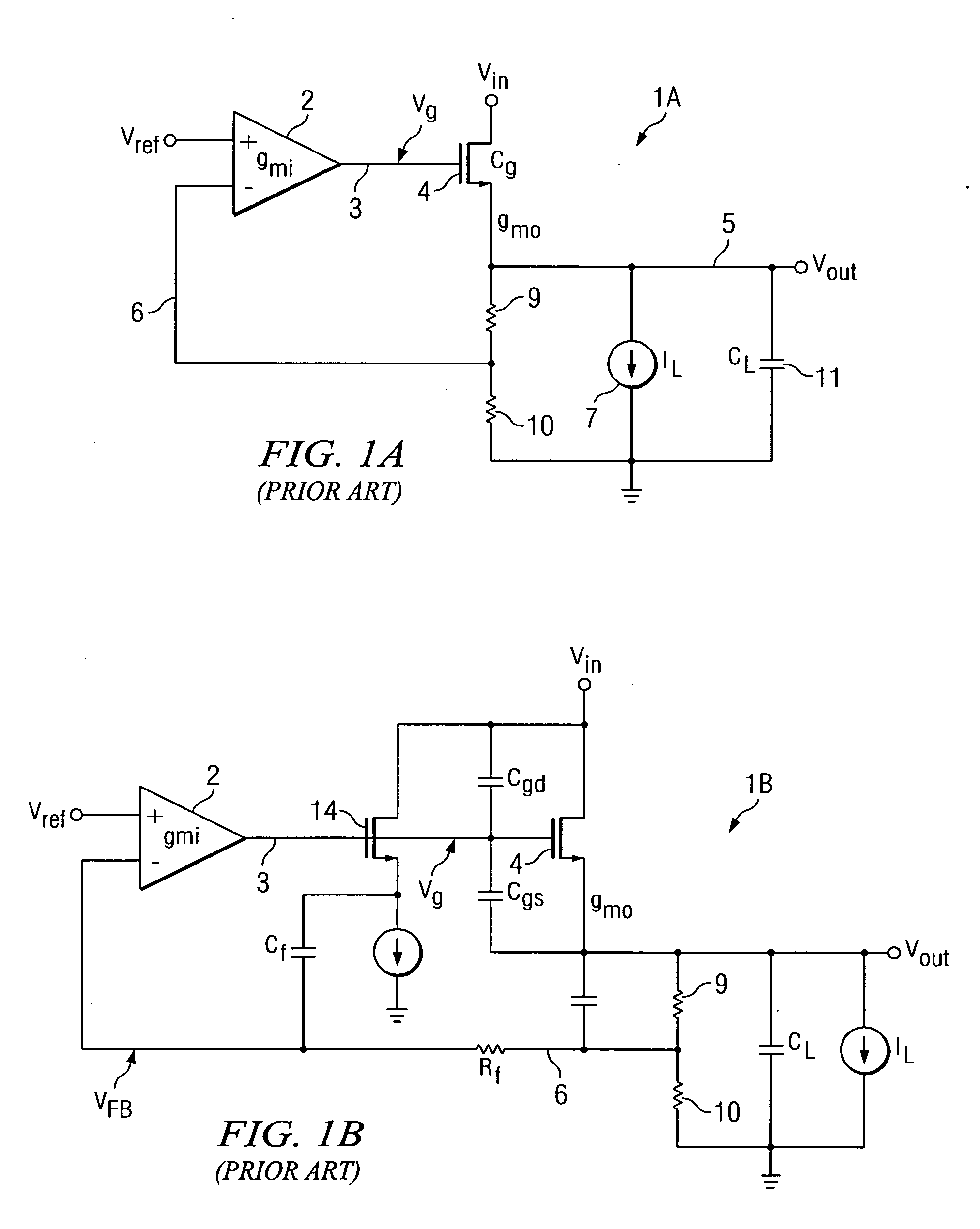
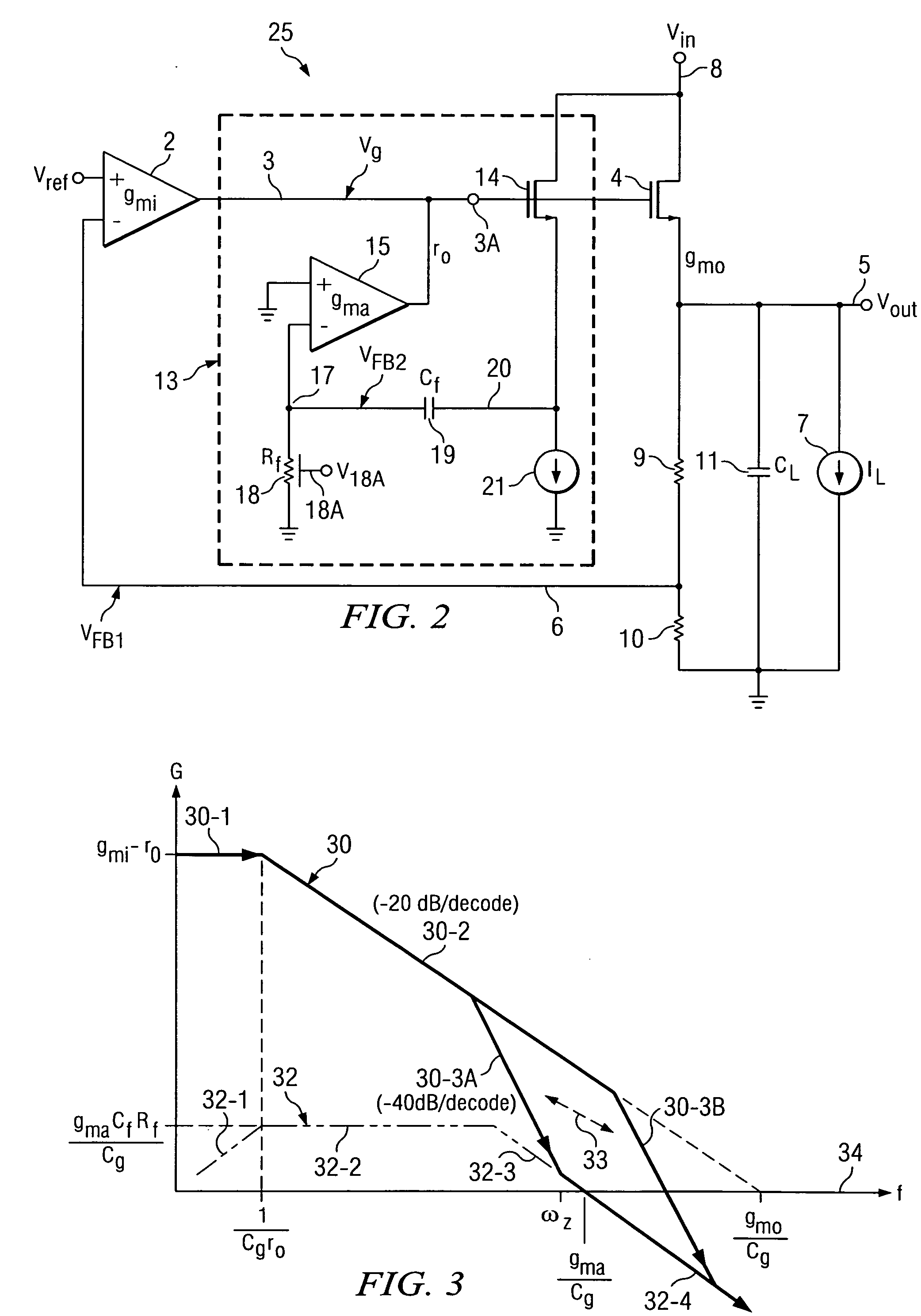
This causes a decrease of the phase margin of LDO regulator 1A as the second pole moves away from the 0 dB line 34 and may result in circuit instability.
However, the use of high ESR tantalum output capacitors compromises the transient performance of the LDO regulator and also may result in capacitor reliability problems because of joule heating effects of the ES are caused by the transient current.
However, this topology was not implemented in the above mentioned TPS731 product for two reasons.
First, the topology was found to be impractical because Cf and Rf need to be large and therefore require too much die area for the signal path to be effective.
Second, Rf can not be too large because that would result in too much noise.

Method used


Image

  • Compensating nmos ldo regulator using auxiliary amplifier
  • Compensating nmos ldo regulator using auxiliary amplifier
  • Compensating nmos ldo regulator using auxiliary amplifier

Examples


Embodiment Construction

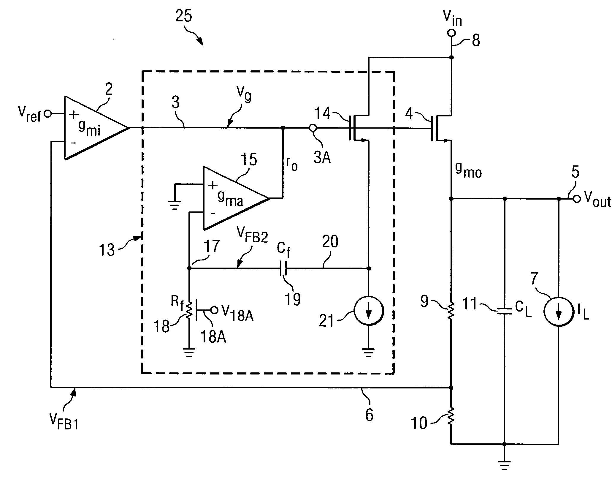
[0023]Referring to FIG. 2, LDO regulator 25 includes an error amplifier 2 having its (+) input coupled to receive reference voltage Vref and its output Vout coupled by conductor 3 to the gate of N-channel pass transistor 4, the drain of which receives unregulated input voltage Vin. The transconductance of error amplifier 2 is gmi, and the output impedance on conductor 3 is r0. The transconductance of pass transistor 4 is gmo. The source of pass transistor 4 produces a regulated output voltage Vout, which can be coupled by output conductor 5 to a load capacitor 11 having a capacitance CL, a load represented by a current source 7 conducting a load current IL, and a voltage divider including a first resistor 9 having a first terminal connected to output conductor 5 and a second terminal connected by feedback conductor 6 to a first terminal of a second resistor 10 having its second terminal connected to ground. A feedback signal VFB1 on conductor 6 is applied to the (−) input of error a...


PUM


Abstract

An LDO (low dropout) regulator including a pass transistor having a first electrode coupled to produce an output voltage of the LDO regulator, a control electrode, and a second electrode coupled to receive an input voltage of the LDO regulator. An error amplifier has a first input coupled to a first reference voltage and an output coupled to the gate control electrode of the pass transistor. A first feedback circuit has an input coupled to the first electrode of the pass transistor and an output producing a first feedback voltage coupled to a second input of the error amplifier. The auxiliary amplifier has a first input coupled to a second reference voltage and an output coupled to the output of the error amplifier. A second feedback circuit has an input coupled to the output of the auxiliary amplifier and an output producing a second feedback voltage coupled to a second input of the auxiliary amplifier. The auxiliary feedback loop is used to take over control of the feedback in the LDO regulator at high frequencies.

Description

BACKGROUND OF THE INVENTION[0001]The present invention relates generally to low dropout (LDO) voltage regulators which have stable operation and high phase margin over wide ranges of output capacitance and effective-series-resistance.[0002]Referring to FIG. 1A, an NMOS LDO regulator 1A includes an error amplifier 2 having its (+) input coupled to receive a reference voltage Vref and its output voltage Vg coupled by conductor 3 to the gate of an N-channel pass transistor 4, the drain of which receives the input voltage Vin which is to be regulated. The source of pass transistor 4 produces a regulated output voltage Vout that is coupled by an output conductor 5 to a load capacitor 11 of capacitance CL to a load IL represented by a current source 7 and to the first terminal of a resistor 9. The second terminal of resistor 9 is connected by a feedback conductor 6 to a first terminal of a second resistor 10 having its second terminal connected to ground. Resistors 9 and 10 form a voltage...

Claims


Application Information

Patent Timeline
IPC IPC(8): G05F1/10
CPCG05F1/575
Inventor WANG, JIANBAO
Owner TEXAS INSTR INC
Learn More