
Multilayer Optical Information Recording Medium, Optical Head, and Optical Drive

Inactive Publication Date: 2008-07-10
RICOH KK
View PDF16 Cites 13 Cited by
  • Summary
  • Abstract
  • Description
  • Claims
  • Application Information

AI Technical Summary

Benefits of technology

[0026]Embodiments of the present invention provide a multilayer optical information recording medium that makes it possible to reduce the fluctuation in the amount of reflected light in recording or reading a signal even when the wavelength or incidence angle of the light varies and thereby to prevent the S / N ratio from decreasing; to accurately position a laser beam even when the number of recording layers is large; and to use various methods to process a control layer and thereby to design the control layer flexibly.
[0030]Another embodiment of the present invention provides an optical head that can accurately detect a signal from a multilayer optical information recording medium according to an embodiment of the present invention.
[0031]Still another embodiment of the present invention provides an optical drive that can accurately record, reproduce, and / or delete information on a multilayer optical information recording medium according to an embodiment of the present invention.

Problems solved by technology

This fluctuation causes an increase in noise and results in a decrease in the S / N ratio.
This makes it difficult to position a laser beam accurately.
Further, since the recording layers are formed just above the control layer, methods that can be used to process the control layer are limited and therefore flexibility in designing the control layer is reduced.
However, if the number of recording layers in a conventional optical disk is increased, the amount of light reflected from a recording layer decreases as the distance between the recording layer and the incidence plane increases, because light is absorbed by other recording layers.
As a result, the amount of light reflected from a distant recording layer decreases to such a level that it is difficult to detect a signal.
Also, a conventional laser diode may not be powerful enough to record information on such a multilayer optical disk.
These problems have been limiting the number of recording layers in an optical disk.
Therefore, in this case, increasing the number of recording layers does not make it difficult to detect a signal or cause recording power shortage problems.
However, as in the case of conventional multilayer disks, forming guide tracks on each of the recording layers results in increased costs.
However, if the recording medium is tilted in the radial direction in relation to the incidence angle of light, a tracking error may occur on a data layer that is distant from the servo layer.
This problem makes it difficult to increase the track density of a recording medium and thereby makes it difficult to increase the storage capacity per data layer.
In this case, however, it is very difficult to accurately align the convexities and concavities on the first and second layers.

Method used


Image

  • Multilayer Optical Information Recording Medium, Optical Head, and Optical Drive
  • Multilayer Optical Information Recording Medium, Optical Head, and Optical Drive
  • Multilayer Optical Information Recording Medium, Optical Head, and Optical Drive

Examples


third embodiment

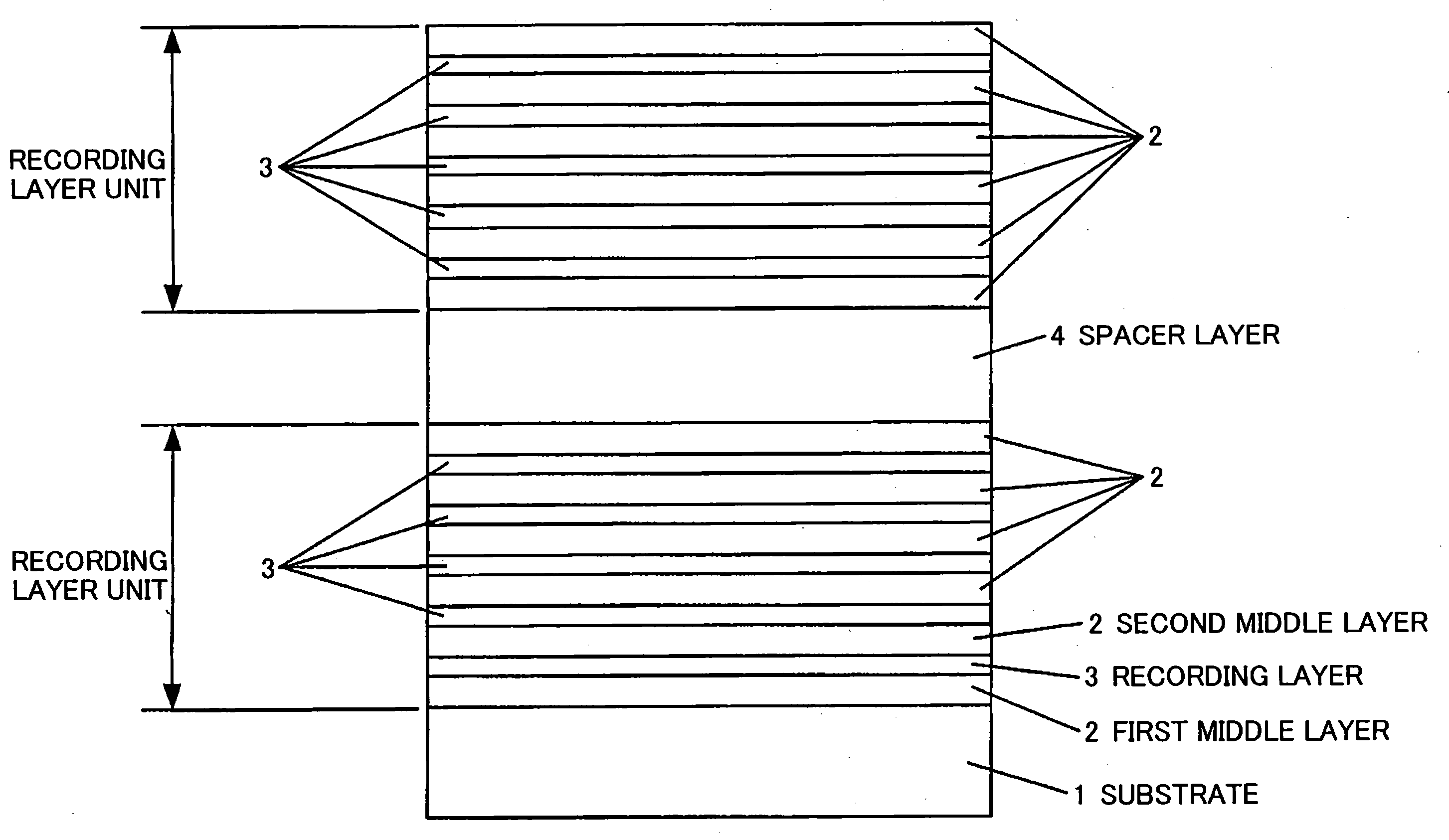
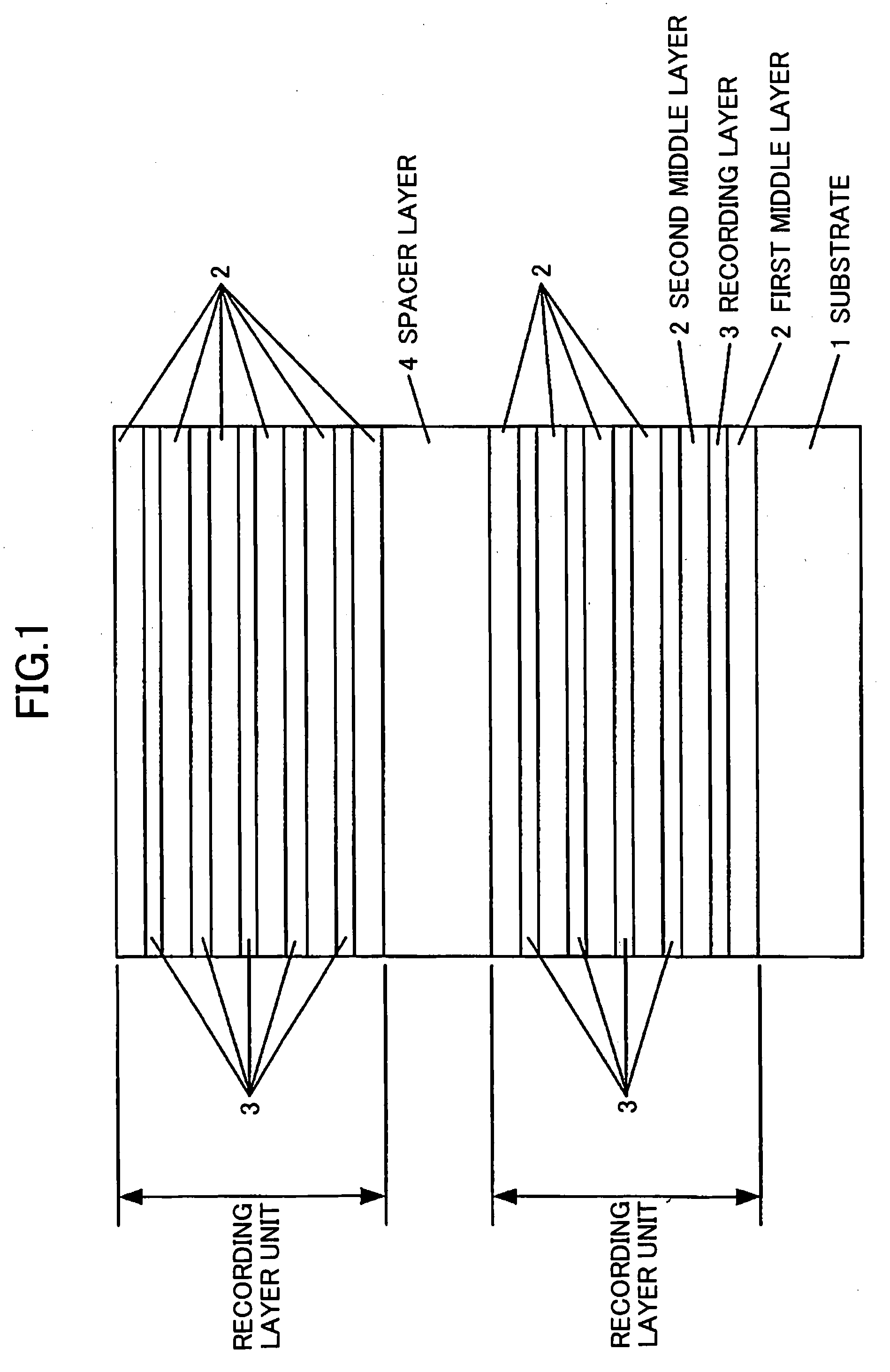
[0091]In the third embodiment, a recording layer unit is made up of five recording layers 3 and six middle layers 2, and one control layer 5 is provided for each recording layer unit. However, the present invention is not limited to this configuration. As a value obtained by a formula [(thickness of recording layer 3)×number of layers+(thickness of middle layer 2)×number of layers] increases, the distance between the control layer 5 and the most distant recording layer 3 increases. In a tracking method that uses light beams from two light sources, a large distance between the control layer 5 and the recording layer 3 results in a low accuracy in positioning a light spot of a recording light beam. For this reason, the number of layers in a recording layer unit is preferably no more than 100.

[0092]In this embodiment, as shown in FIG. 5, grooves are formed on a surface of the control layer 5, which surface is closer to the substrate 1, to detect a tracking error using a push-pull metho...

eleventh embodiment

[0101]FIG. 13 is a drawing illustrating the configuration of an exemplary signal recording / reproducing apparatus according to the present invention for recording and reproducing a signal on a multilayer optical information recording medium according to an embodiment of the present invention. In this embodiment, the third exemplary multilayer optical information recording medium shown in FIG. 5 is used as an exemplary optical recording medium to describe exemplary signal recording and reproduction processes by the exemplary signal recording / reproducing apparatus.

[0102]The eleventh embodiment of the present invention is described below with reference to FIG. 13. In the exemplary signal recording / reproducing apparatus shown in FIG. 13, a light beam emitted from a light source 11 (first light source) passes through a lens 12, a polarization beam splitter 13, a dichroic prism 14, a ¼ wavelength plate 15, and an objective lens 16; and is thereby focused on a track on the control layer 5 i...


PUM


Abstract

A disclosed optical recording medium includes multiple recording layer units in each of which one or more recording layers and one or more middle layers are stacked alternately; and one or more spacer layers. In the disclosed optical recording medium, the recording layer units and the spacer layers are stacked alternately in a depth direction of the optical recording medium.

Description

TECHNICAL FIELD[0001]The present invention generally relates to a multilayer optical information recording medium, an optical head, and an optical drive, and more particularly relates to a multilayer optical information recording medium with multiple recording layers, an optical head for the multilayer optical information recording medium, and an optical drive capable of recording, reproducing, and / or deleting information on the multilayer optical information recording medium.BACKGROUND ART[0002]Patent document 1 discloses a method of optically writing, reading, and / or deleting information on a conventional multilayer optical information recording medium having at least two recording layers and two guide layers; and an apparatus for writing, reading, and / or deleting information on the conventional multilayer optical information recording medium. FIG. 14 shows the structure of an exemplary recording medium described in patent document 1. The exemplary recording medium includes multip...

Claims


Application Information

Patent Timeline
IPC IPC(8): G11B3/74G11B7/24038
CPCB82Y10/00G11B7/24038G11B7/0938
Inventor MISAWA, SHIGEYOSHIOOUCHIDA, SHIGERU
Owner RICOH KK
Learn More