Eureka AIR delivers breakthrough ideas for toughest innovation challenges, trusted by R&D personnel around the world.

Apparatus and method for producing sustainable power and heat

a technology of power and heat energy, applied in mechanical apparatus, machines/engines, steam engine plants, etc., to achieve the effect of minimizing power losses and optimizing the conversion of heat energy into electrical power

Inactive Publication Date: 2008-07-10
OBRIEN KEVIN M
View PDF8 Cites 68 Cited by
  • Summary
  • Abstract
  • Description
  • Claims
  • Application Information

AI Technical Summary

Benefits of technology

"The present invention is an integrated system that can provide both electric power and heat from various energy sources such as solar, waste heat, biomass, and fossil fuels. The system uses a volatile organic working fluid that circulates in a variable speed heat engine type cycle, with the fluid heated to its boiling point, a saturated state, or a superheated gas state, and then cooled in a condenser. The system can produce electricity that is interconnected to the grid and can also operate independently of the grid when the grid fails. The system can also dynamically control the amount and ratio of electrical to thermal output and optimize the conversion of heat energy into electrical power while minimizing power losses. Additionally, the system can recover waste heat from sources like air conditioning and refrigeration systems and use it to generate electric power and useful heat."

Problems solved by technology

While the above-described systems fulfill their respective, particular objectives and requirements, the aforementioned systems do not describe a system that uses beneficial portions of the Rankine and Carnot cycles to produce electricity and heat at minimal amounts of energy.

Method used


Image

  • Apparatus and method for producing sustainable power and heat
  • Apparatus and method for producing sustainable power and heat
  • Apparatus and method for producing sustainable power and heat

Examples


Embodiment Construction

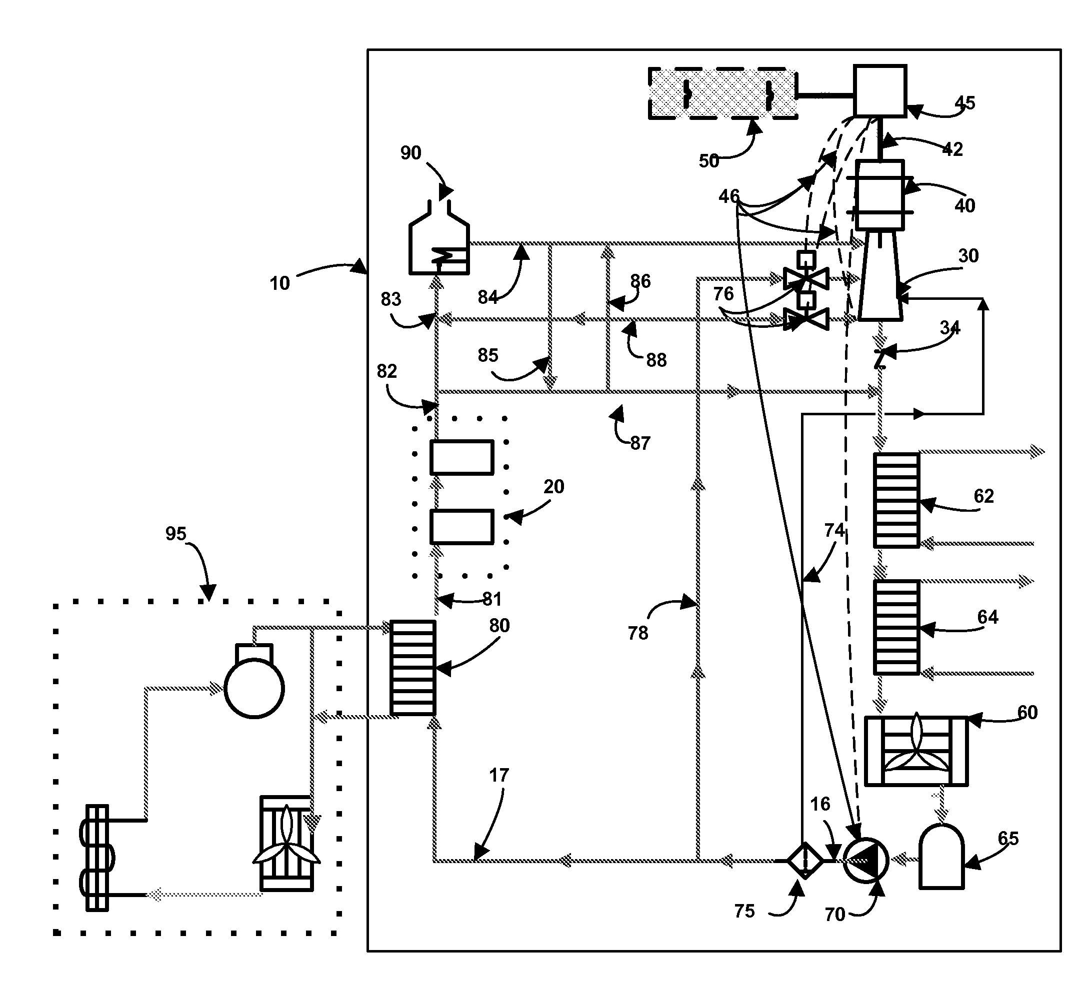
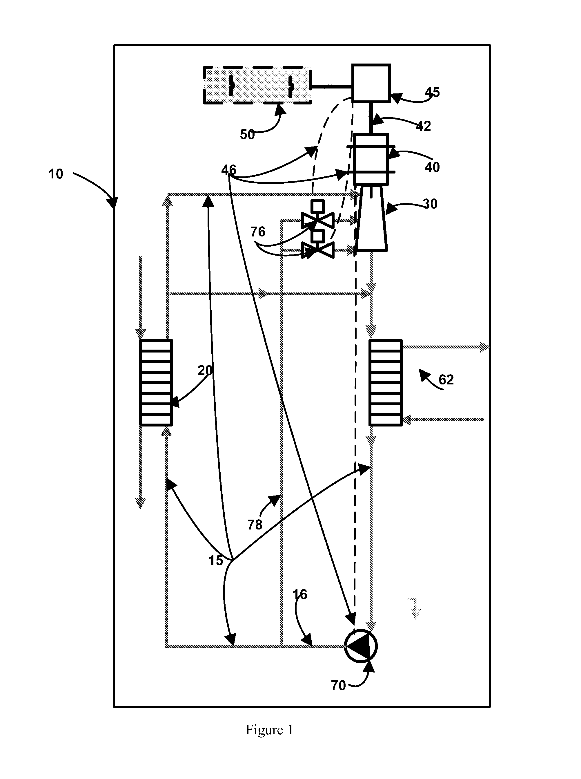
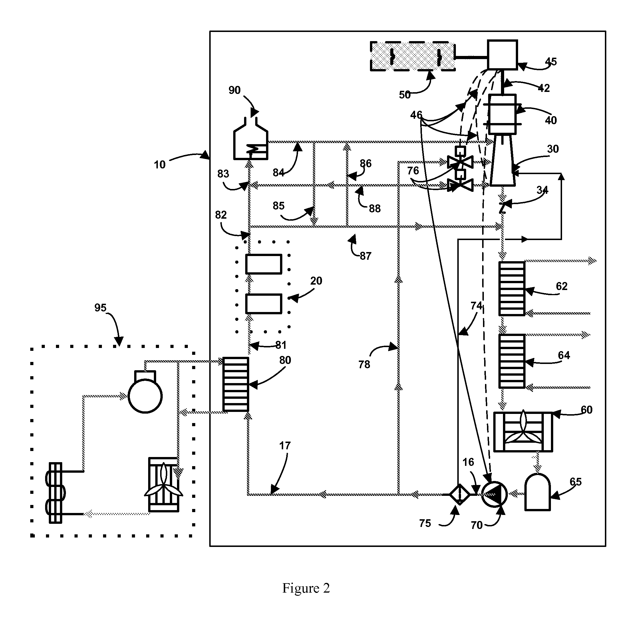
[0031]The present art overcomes the prior art limitations by providing a combined electricity and heat producing system fueled by various sources, primarily solar and other renewable sources integrated with combustion of fossil fuels for a supplemental heat source. With reference to the drawings, FIG. 1 illustrates a possible configuration of the principal hardware components comprising a system embodying the operating mechanisms to affect the benefits described. It is noted however that variations in equipment may be made and would be within the ambit of a person skilled in the art. Referring initially to FIG. 1, one embodiment of the integrated Combined Heat and Power System 10 is a directly-heated, single closed loop system that includes a first (or primary) circuit thermal fluid conduit 15 and a secondary circuit thermal fluid conduit 78. An advantage of the directly heated system is that it eliminates the inherent loss resulting from the pinch points of the various heat sources...


PUM


Abstract

An integrated system provides electricity and heat from solar, waste heat, biomass and fossil fuel energy. The system operates with a volatile organic working fluid that circulates in a variable speed heat engine type cycle, that is heated either to its boiling point, to a saturated state or above its boiling point, or to a superheated gas state, expanded through an expander, with working fluid injected therein such that the fluid exiting the expander is cooled in a condenser in thermal communication with a facility's domestic hot water, space heating or process heating systems, and circulated by a pump. Heat exchange loops define hot water production capability for use in a facility while a generator is coupled to the expander to produce electricity and is connected to the utility grid at fixed frequency and voltage in either a paralleling or island mode.

Description

BACKGROUND OF THE INVENTION[0001]The present invention relates generally to the onsite production of heat and power from sustainable resources such as solar, waste heat and biomass system for the supply of electrical power, domestic hot water and space heating operating either in parallel or in isolation from the central grid, and more specifically, to a modular, scalable systems that enables maximum harvesting of solar energy, waste heat energy and heat from the combustion of fuel, to produce electrical power and useable heat in a closed loop heat engine cycle using a volatile organic working fluid in a system dynamically responsive to the source temperature, sink temperature, facility's electrical and thermal loads and ambient conditions.[0002]In recent years, six major trends have emerged that are reshaping the energy industry. First, millions of consumers have experienced more frequent, more prolonged and more devastating electrical outages from failure of the central grid cause...

Claims


Application Information

Patent Timeline
Patent Type & Authority Applications(United States)
IPC IPC(8): F01K17/02F01K25/00F01K25/08
CPCY02E20/14F01K25/08
Inventor O'BRIEN, KEVIN M.
Owner OBRIEN KEVIN M
Why Eureka
Eureka Blog
Learn More