
Power device package

a technology of power devices and power supply cables, applied in semiconductor devices, semiconductor/solid-state device details, electrical apparatus, etc., can solve the problems of difficult to achieve reliable bonding of gold wires with interconnection patterns, failure to ensure reliable electrical contact with only nickel or copper layers, etc., to achieve reliable electrical connection and low cost

Active Publication Date: 2008-07-03
SEMICON COMPONENTS IND LLC
View PDF45 Cites 13 Cited by
  • Summary
  • Abstract
  • Description
  • Claims
  • Application Information

AI Technical Summary

Benefits of technology

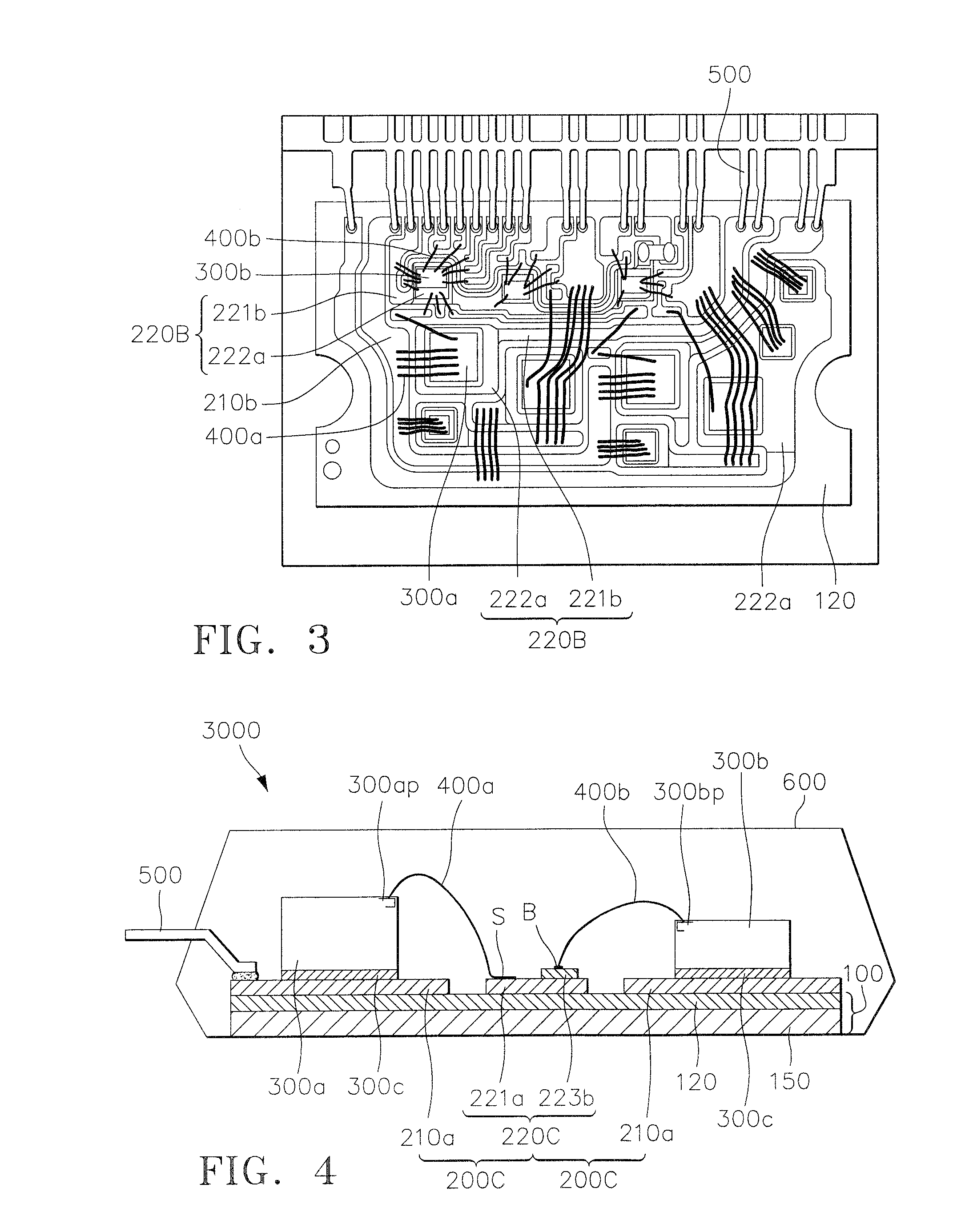
[0014]The power device package according to the present invention includes an interconnection pattern including a metal single conductive layer and a multiple conductive layer disposed on an insulating substrate, so that reliable electrical connections for different wires with different specifications, e.g., different thicknesses and materials, can be realized. Also, according to the present invention, since the multiple conductive layer may be formed using an electroless plating method and a wet etching method, the power device package can be manufactured at a low cost.

Problems solved by technology

But we found that even when a surface oxidation layer is formed on the nickel layer or the copper layer, the heavy wire connected to the power control semiconductor chip could ensure reliable electrical contact with the nickel layer or the copper layer by mechanically passing through the surface oxidation layer, however, the small wire connected to the low power semiconductor chip failed to ensure reliable electrical contact with only the nickel layer or the copper layer.
In particular, when a gold wire was used as the small wire, it was difficult to achieve reliable bonding of the gold wire with the interconnection pattern because of the surface oxidation layer formed on the nickel layer or the copper layer.

Method used


Image

  • Power device package
  • Power device package
  • Power device package

Examples


Embodiment Construction

[0023]The present invention will now be described more fully with reference to the accompanying drawings, in which exemplary embodiments of the invention are shown.

[0024]The invention may, however, be embodied in many different forms and should not be construed as being limited to the embodiments set forth herein; rather, these embodiments are provided so that this disclosure will be thorough and complete, and will fully convey the concept of the invention to those skilled in the art. It will also be understood that when a layer is referred to as being “on” another layer or substrate, it can be directly on the other layer or substrate, or intervening layers may also be present. In the drawings, the thicknesses and sizes of layers and regions are exaggerated for clarity, and like reference numerals in the drawings denote like elements. The terms “and / or” used herein includes any and all combinations of one or more of the associated listed items.

[0025]Also, though terms like a first, ...


PUM


Abstract

A power device package according to the one embodiment of the present invention includes an insulating substrate with an interconnection pattern disposed on the insulating substrate. The interconnection pattern comprises a single conductive layer comprising a first metal layer, and a multiple conductive layer comprising another first metal layer and a second metal layer disposed on the another first metal layer. A plurality of wires are attached to an upper surface of the single conductive layer and / or an upper surface of the second metal layer of the multiple conductive layer. Contact pads on a power control semiconductor chip and a low power semiconductor chip driving the power control semiconductor chip are electrically connected to the wires.

Description

CROSS-REFERENCE TO RELATED PATENT APPLICATION[0001]This application claims the benefit of Korean Patent Application No. 10-2006-0137730, filed on Dec. 29, 2006, in the Korean Intellectual Property Office, the disclosure of which is incorporated herein in its entirety by reference.BACKGROUND OF THE INVENTION[0002]1. Field of the Invention[0003]The present invention relates to a power device package, and more particularly, to a power device package including a printed circuit board.[0004]2. Description of the Related Art[0005]Recent developments in power electronics including such devices as servo drivers, inverters, power regulators, and converters are leading to increasing demands for light, small power devices with excellent performance characteristics. Therefore, research is being actively conducted into smart or intelligent power modules in which a variety of power semiconductor chips and low power semiconductor chips, such as IC chips for controlling the power semiconductor chip...

Claims


Application Information

Patent Timeline
Patent Type & Authority Applications(United States)
IPC IPC(8): H01L23/495
CPCH01L23/49531H01L24/48H01L24/45H01L24/49H01L2224/45015H01L2224/45124H01L2224/45144H01L2224/48091H01L2224/4903H01L2224/49051H01L2224/49171H01L2224/73265H01L2924/01005H01L2924/01013H01L2924/01014H01L2924/01028H01L2924/01029H01L2924/01074H01L2924/01078H01L2924/01079H01L2924/01082H01L2924/14H01L2924/20752H01L2924/20753H01L2924/20754H01L2924/20755H01L2924/20756H01L2924/20757H01L2924/2076H01L23/49575H01L2224/32225H01L2224/49111H01L2224/48227H01L2224/48137H01L2924/014H01L2924/01033H01L2924/00014H01L2924/00H01L2224/48139H01L2924/181H01L2224/0603H01L2924/00012
Inventor LEE, JOO-SANGJEON, O-SEOBKWON, YONG-SUKCHEN, FRANKZHU, ADAMS
Owner SEMICON COMPONENTS IND LLC
Learn More