
Vehicle device

a technology for vehicles and antennas, applied in the field of vehicles, can solve the problems of restricting the warning provision timing only for traveling vehicles, unsafe operation, and the above-mentioned vehicle device has the following problems, so as to prevent the number of antennas disposed along the road, the effect of reducing the number of antennas

Inactive Publication Date: 2008-06-26
DENSO CORP
View PDF12 Cites 34 Cited by
  • Summary
  • Abstract
  • Description
  • Claims
  • Application Information

AI Technical Summary

Benefits of technology

[0011]The vehicle device and the roadside device of the present invention configured as described above provides the user with useful information through only a few roadside devices at an entrance / exit of, for example, a service area, a parking area or the like. Therefore, the number of antennas disposed along a road is reduced and the user is prevented from being distracted due to an avoidance of unnecessary information provision.

Problems solved by technology

However, the vehicle device described above has following problems.
However, in the above warning provision scheme, card insertion is determined only when the vehicle device communicates with the roadside device, thereby making it necessary to have may antennas installed along the road.
In addition, the antenna is usually installed over the road due to a communication range requirement, thereby restricting warning provision timing only for traveling vehicles.
As a result, the user, that is, a driver of the vehicle, is distracted from driving operation to check an insertion condition of the card, which may lead to an unsafe operation.
That is, for example, when the information provision area is set at the SA / PA, the information notification is served for the user before he / she pulls out the card from the vehicle device, thereby causing a goal of card insertion confirmation prior to a departure from the SA / PA unachievable.

Method used


Image

  • Vehicle device
  • Vehicle device
  • Vehicle device

Examples


Embodiment Construction

[0018]Embodiments of the present disclosure are described with reference to the accompanying drawings.

[0019]The embodiment which the present invention is applied to as follows is described with a drawing. In addition, the form of the enforcement of the present invention can adopt various kinds of forms without being limited to the following embodiment as far as it pertains to the technical field of the present invention.

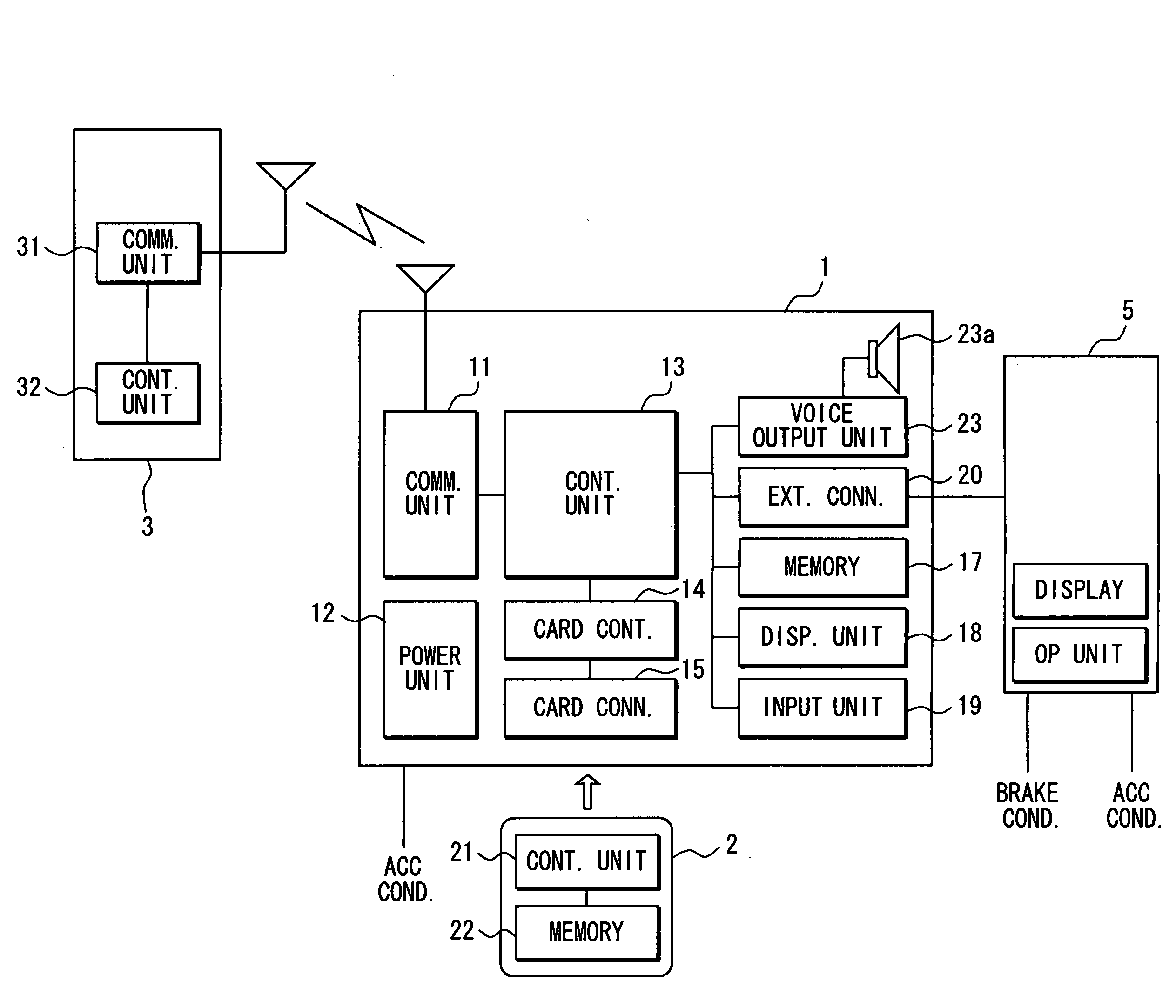
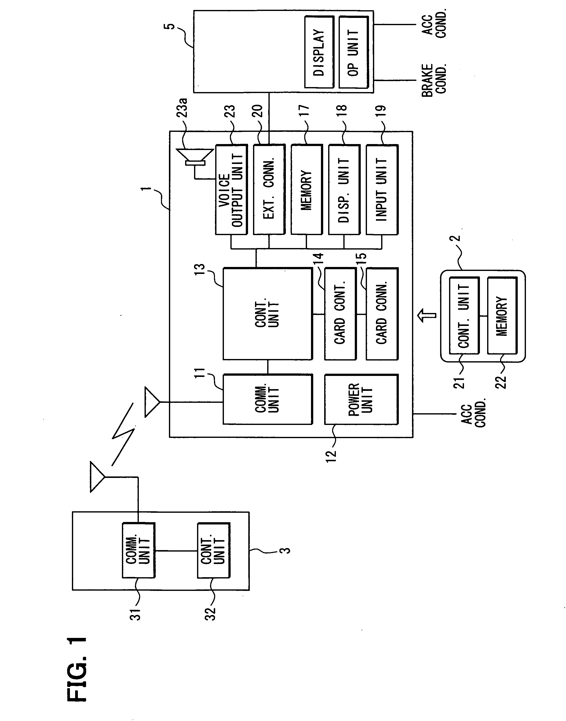
[0020]An embodiment of an in-vehicle device 1 of the present embodiment is described with reference to FIG. 1. FIG. 1 is a block diagram showing an in-vehicle device 1, a multifunctional IC card (an IC card hereinafter) 2, and a roadside device 3. (Configuration of In-vehicle device 1 and roadside device 3) The in-vehicle device 1 has a communication unit 11, a power unit 12, a control unit 13, a card controller 14, a card connector 15, a memory 17, a display unit 18, an input unit 19, an external connector 20, and a voice output unit 23. The device 1 is an in-vehicl...


PUM


Abstract

A vehicle device for use in vehicle-roadside communication that communicates with a roadside device disposed on a roadside includes a radio unit for receiving an informational message from the roadside device as well as a display and a speaker for information provision. The vehicle device further includes a storage unit for storing the informational message received by the radio unit. A system controller in the vehicle device determines whether information provision condition for providing the informational message in the storage unit is met based on an information content and current condition information in the informational message received by the radio unit. When the information provision condition is determined to be met, the system controller controls the display and the speaker to cause a provision of the informational message.

Description

CROSS REFERENCE TO RELATED APPLICATION[0001]This application is based on and claims the benefit of priority of Japanese Patent Application No. 2006-348282 filed on Dec. 25, 2006, the disclosure of which is incorporated herein by reference.FIELD OF THE INVENTION[0002]The present disclosure generally relates to a vehicle device for use in a vehicle to provide a user with useful information.BACKGROUND INFORMATION[0003]Conventionally, a vehicle device is used for vehicle-roadside communication between the vehicle device disposed on the vehicle and a roadside device disposed on a roadside of a traveling vehicle.[0004]A certain vehicle device watches a pulling out of a card in the unit by using a card detector when a user leaves the card in the vehicle device, and provides a large warning sound from a speaker when the card is pulled out by a thief (refer to Japanese patent document JP-A-2003-132387). The vehicle device in the above patent document makes the thief run off from the vehicle ...

Claims


Application Information

Patent Timeline
IPC IPC(8): B60Q1/00G08G1/09H04W4/00G07B15/00H04W4/04
CPCG07B15/063G07B15/02
Inventor SHAMOTO, MICHIO
Owner DENSO CORP
Learn More