Eureka AIR delivers breakthrough ideas for toughest innovation challenges, trusted by R&D personnel around the world.

Welding Job Sequencer

Active Publication Date: 2008-06-26
LINCOLN GLOBAL INC
View PDF39 Cites 150 Cited by
  • Summary
  • Abstract
  • Description
  • Claims
  • Application Information

AI Technical Summary

Problems solved by technology

However, their repeating operations cannot easily adapt to varying welding conditions and / or sequences.
In contrast, semi-automatic work cells (i.e., work cells involving at least some operator welding) generally provide less automation vis-à-vis robotic work cells, and accordingly have a relatively higher labor cost and a relatively lower productivity.
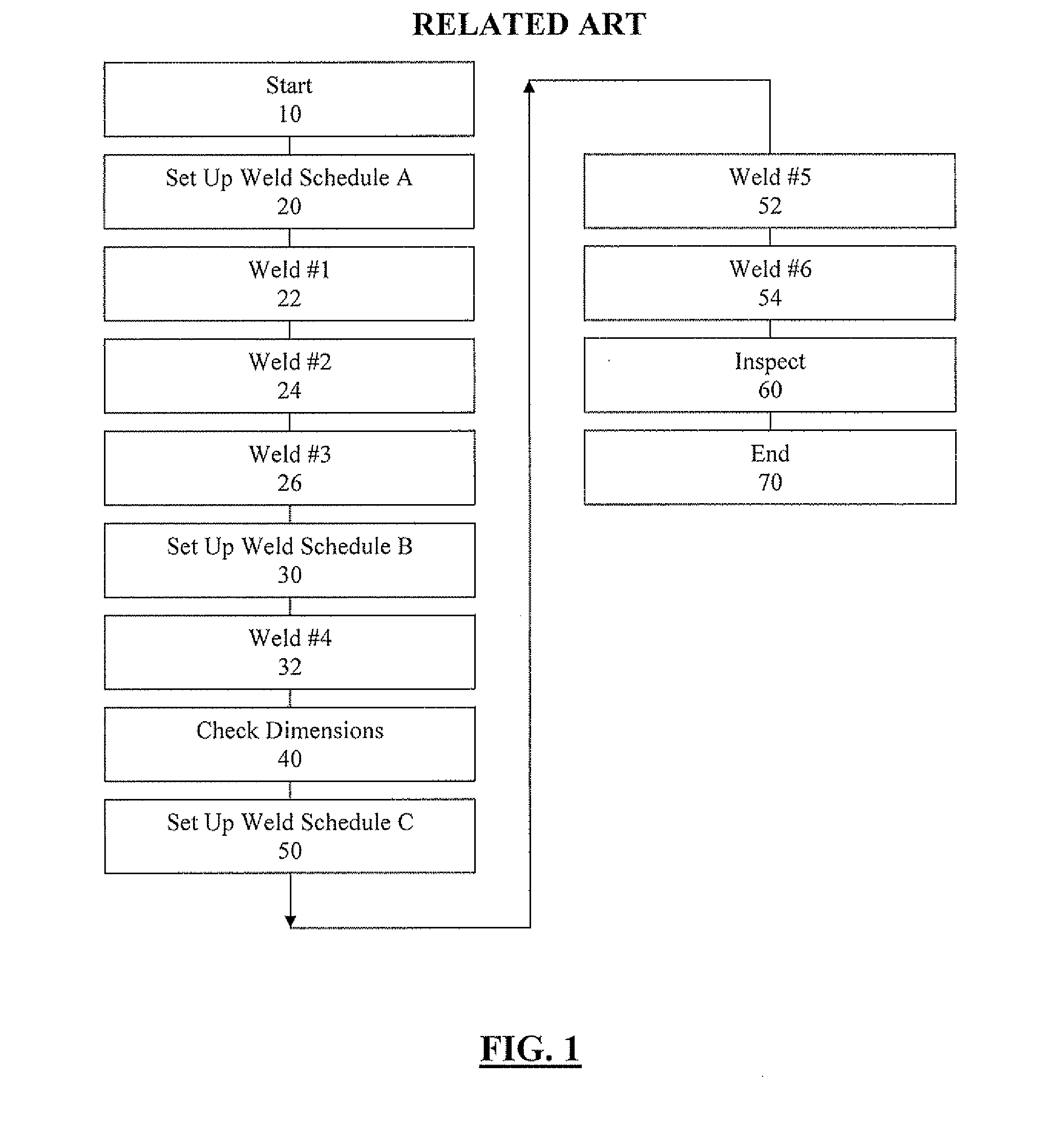
Unfortunately, when welding more complex assemblies in related art semi-automatic work cells, multiple different welding schedules are often required for different types of welds on different parts of an assembly.
Nevertheless, even in such systems, the operator still needs to cease welding operations and push a button to select the new welding schedule before he may continue welding.
While this reduction of welding schedules makes the overall operation easier for the welder, the forced simplification of this approach can lead to reduced productivity and lower overall quality.
However, in a semi-automatic work cell, these requirements are susceptible to human error, since the operator must keep track of all of these aspects in addition to performing the welding operations themselves.
Errors in any of these responsibilities can result either in rework (if the errors are caught during inspection at operation 60) or a defective part being supplied to the end user.
Further, this exemplary semi-automatic welding method hampers productivity, because the operator must spend time configuring and reconfiguring weld schedules.

Method used


Image

  • Welding Job Sequencer
  • Welding Job Sequencer

Examples


Embodiment Construction

[0021]Exemplary embodiments of the invention will now be described below by reference to the attached Figures. The described exemplary embodiments are intended to assist the understanding of the invention, and are not intended to limit the scope of the invention in any way. Like reference numerals refer to like elements throughout.

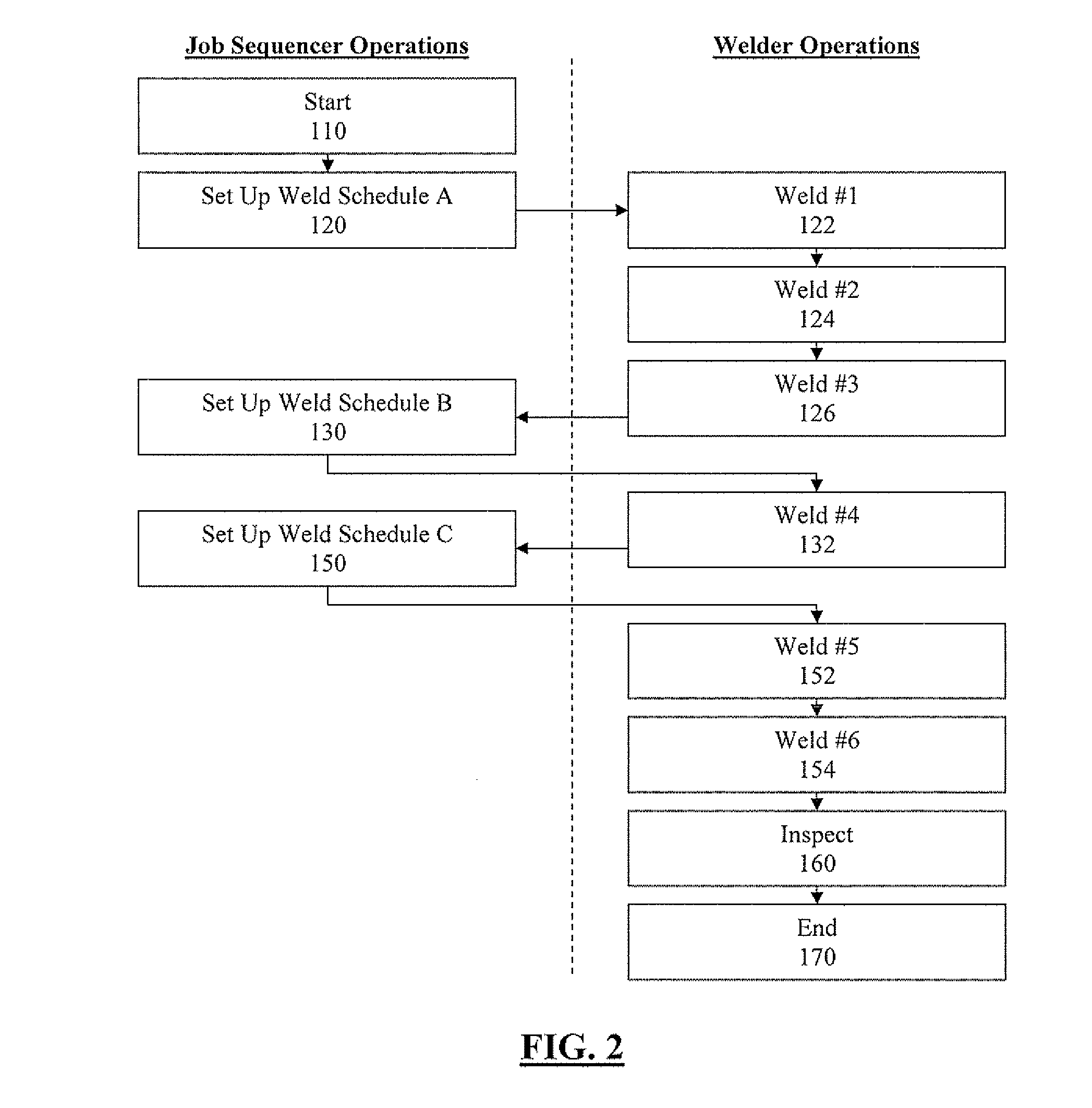
[0022]In an exemplary embodiment of the invention, a welding job sequencer is provided. The welding job sequencer improves the semi-automatic work cell of the related art by increasing the productivity of the semi-automatic work cell without compromising the number of weld schedules usable therein. The welding job sequencer accomplishes this improvement by implementing automatic changes in the semi-automatic work cell, and by providing the operator with an array of commands and instructions.

[0023]More specifically, in an exemplary embodiment, the welding job sequencer automatically selects and implements a function of the welding work cell. An example of s...


PUM

PropertyMeasurementUnit
Timeaaaaaaaaaa
Sizeaaaaaaaaaa
Energyaaaaaaaaaa

Abstract

A semi-automatic welding work cell, including a welding job sequencer that automatically selects a welding schedule for use by an operator in the semi-automatic welding work cell. The automatic selection may be by way of elapsed time, a detection of welding operations, a detection of the amount of welding wire supplied for the welding operation, or a detection of the amount of energy supplied for the welding operation.

Description

BACKGROUND OF THE INVENTION[0001]1. Field of the Invention[0002]Devices, systems, and methods consistent with the invention relate to semi-automatic welding work cells.[0003]2. Description of the Related Art[0004]In the related art, work cells are used to produce welds or welded parts. There are at least two broad categories of work cells, including robotic work cells and semi-automatic work cells.[0005]In robotic work cells, the scheduling and performing of welding operations is largely automated, with little operator involvement. Thus, these cells generally have a relatively low labor cost and a relatively high productivity. However, their repeating operations cannot easily adapt to varying welding conditions and / or sequences.[0006]In contrast, semi-automatic work cells (i.e., work cells involving at least some operator welding) generally provide less automation vis-à-vis robotic work cells, and accordingly have a relatively higher labor cost and a relatively lower productivity. N...

Claims


Application Information

Patent Timeline
IPC IPC(8): B23Q15/20
CPCG05B19/41865G05B2219/45135G05B2219/32007G05B2219/32001B23K9/095B23K9/10B23K9/0953Y02P90/02B23K31/125
Inventor DANIEL, JOSEPH A.BRANT, DMITRY
Owner LINCOLN GLOBAL INC
Why Eureka
Eureka Blog
Learn More