Automated Manufacturing Machine

a manufacturing machine and automatic technology, applied in the field of automatic machines, can solve the problems of difficult manufacturing of magnetic cores for such devices, not often possible, and all suffer from a lack of precision in the positioning of the apertures

Active Publication Date: 2008-06-26
REGAL BELOIT AUSTRALIA PTY LTD
View PDF5 Cites 13 Cited by
  • Summary
  • Abstract
  • Description
  • Claims
  • Application Information

AI Technical Summary

Benefits of technology

[0026]The control means is arranged to provide very accurate control of the mandrel indexing means. This ensures the accuracy of the slot being formed in the roll of material on the mandrel. It will also be appreciated that variation in the shape of the slots formed in the roll of material on the mandrel may be produced by varying the functional operation of the control means, without need to vary the physical construction or restraints of the punch and wind machine.
[0040]Preferably, after one complete rotation of the mandrel, a permanent fixing means is applied to attach a first layer of material on the mandrel to a second layer so as to thereby prevent an inside diameter of the roll of material from unwinding when it is removed from the mandrel.
[0045]A fixing means may then be used to fix the ends of the roll to prevent inadvertent unwinding of the roll.

Problems solved by technology

However, it is recognised that the manufacture of the magnetic core for such devices is difficult.
It will be appreciated by those skilled in the art that the difficulty when producing this form of core is to ensure that the apertures are punched in the material so that they align properly to form the required “straight sided” radial slots.
Unfortunately, this is not often possible because of the difficulty in maintaining the material between the punch and die arrangement 6 and the roll 2 in a horizontal orientation.
Although other forms of machines have been developed to manufacture cores with “straight sided” radial slots, they all suffer from a lack of precision with regard to the positioning of the punched apertures.

Method used


Image

  • Automated Manufacturing Machine
  • Automated Manufacturing Machine
  • Automated Manufacturing Machine

Examples


Embodiment Construction

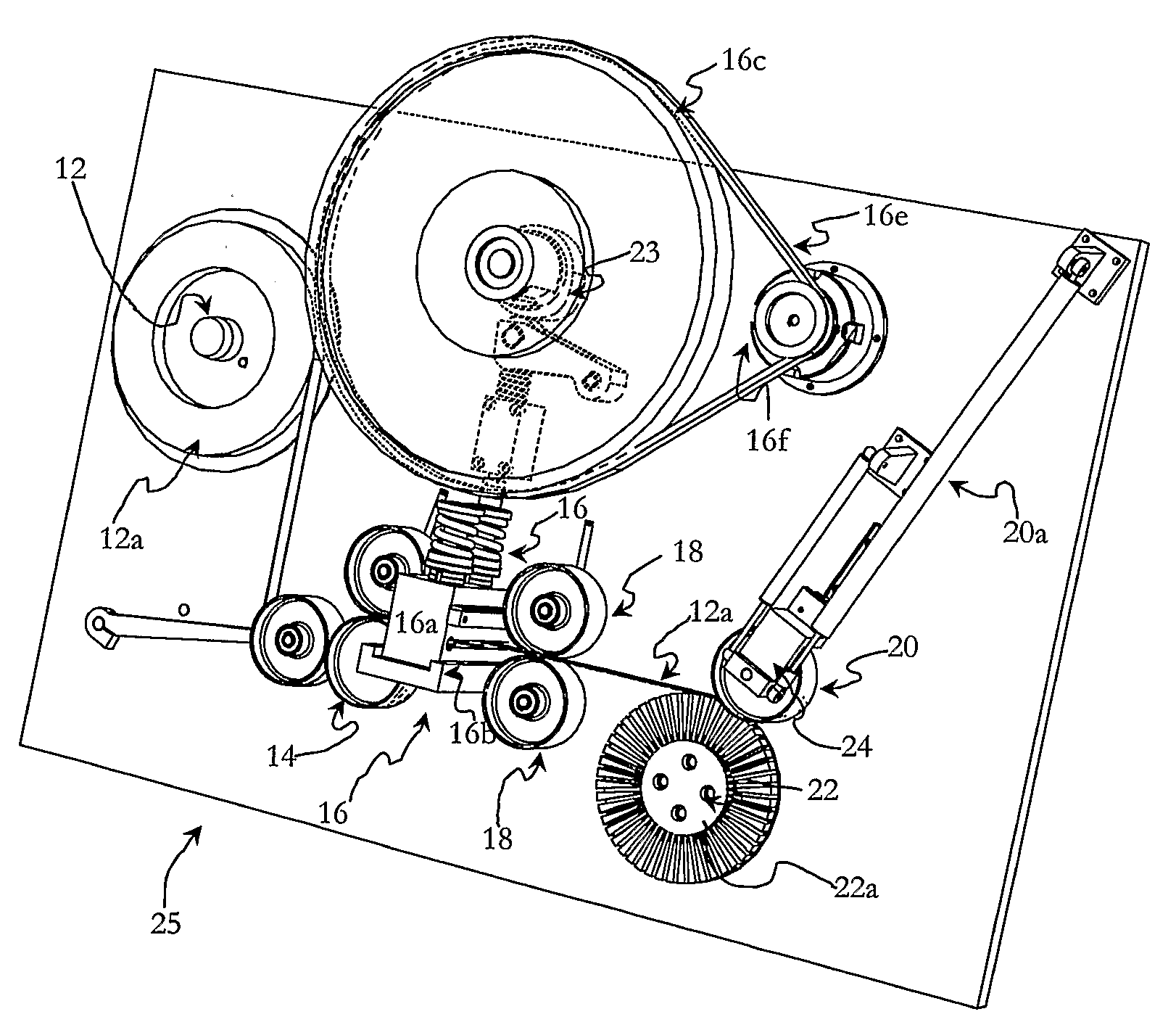
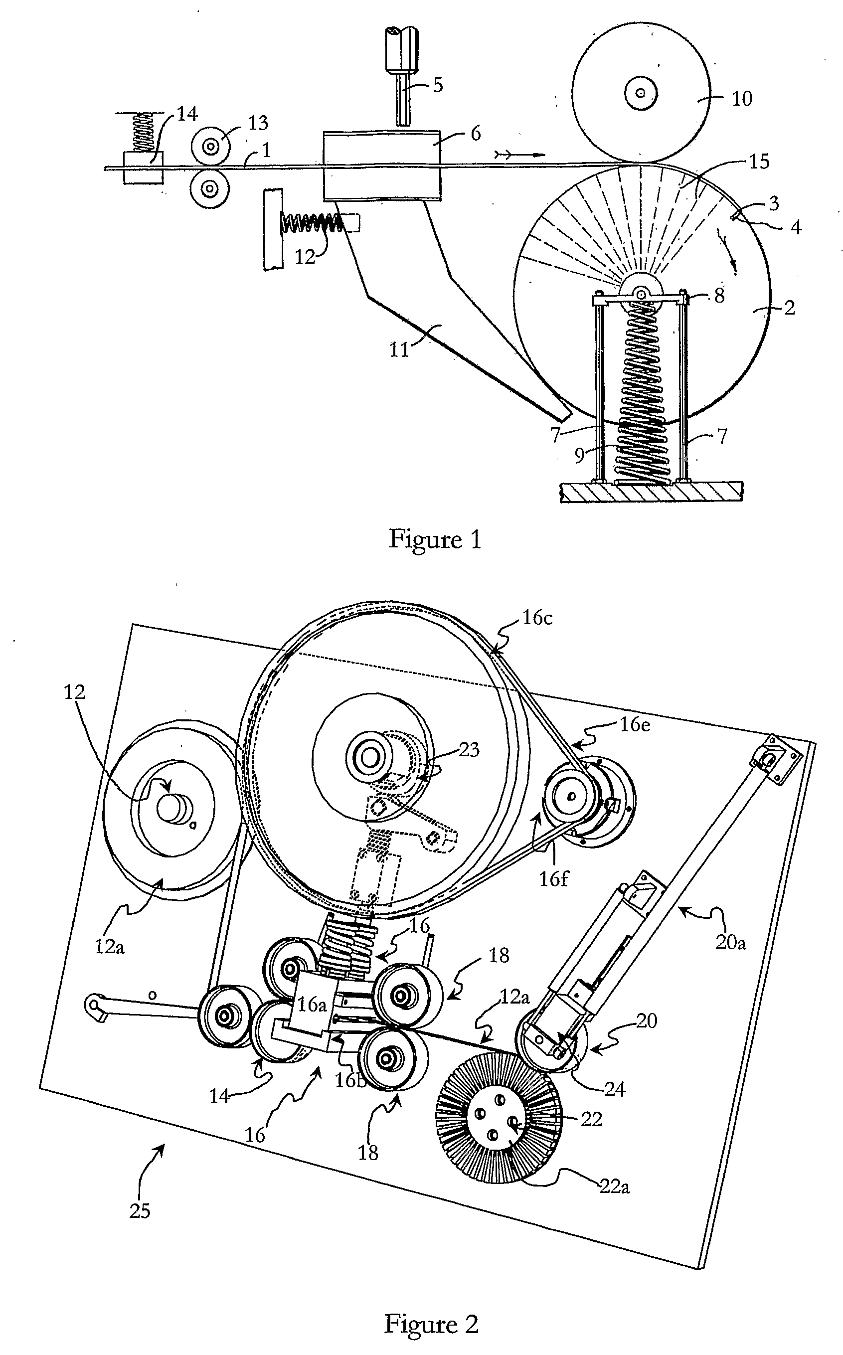
[0055]FIG. 2 illustrates a punch and wind machine 25 in accordance with an embodiment of the invention. The machine 25 includes a material spool mount 12, a tensioning roller set 14, a punch and die arrangement 16, a pair of stabilising rollers 18, a build roller 20 and a mandrel 22.

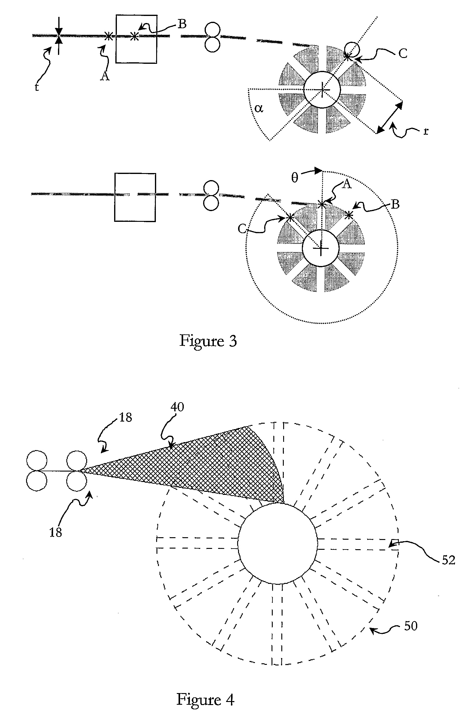
[0056]The spool mount 12 is arranged to receive a roll of material 12a which when punched by the punch and die arrangement 16 and then rolled onto the mandrel 22 forms a core 50 having “axial flux” geometry. In other words, the core 50 (FIG. 5) includes a plurality of “straight sided” slots 52 formed therein.

[0057]The punch and die arrangement 16 includes a punch 16a, a die 16b, a flywheel 16c and a spring biased push rod 16d. The flywheel 16c is driven via a drive belt 16e and a drive pulley 16f. A cam 23 initiates movement of the spring biased push road 16d which drives the punch 16a towards the die 16b. This results in the formation of an aperture in the material 12a.

[0058]The machine 25 is arranged ...


PUM

PropertyMeasurementUnit
Lengthaaaaaaaaaa
Thicknessaaaaaaaaaa
Angleaaaaaaaaaa

Abstract

The present invention provides a method and machine for producing a slotted wound core (50). The machine includes a punch arrangement (16) arranged to punch apertures in a length of material (12a), a mandrel (22) for receiving the punched material, a control means and a mandrel indexing means. The positioning of the punch arrangement (16) and the mandrel (22) is fixed and the mandrel (22) is arranged to be rotated by the mandrel indexing means after each operation of the punch arrangement so that a roll of punched material is formed on the mandrel (22). The mandrel (22) is rotated by an amount (&ggr;) determined by the control means. The control means determines the indexed amount so that selected apertures punched in the length of material align with one another when the material (12a) is rolled onto the mandrel (22) so that the aligned apertures form respective slots (52) of a desired configuration in the core (50).

Description

FIELD OF THE INVENTION[0001]This invention relates to an automated machine for producing a slotted wound product by punching and winding a length of material. The machine has particular, but not exclusive application for the manufacture of cores of the type found in electric motors and the like.BACKGROUND OF THE INVENTION[0002]Devices such as electric motors, generators and transformers include a magnetically conducive base which is generally known as a “stator”. The stator includes a core and a winding. The winding is typically a copper winding which is located within the slots formed in the core.[0003]Stators typically adopt either one of two basic geometries. The first geometry is known as “radial flux” and the second geometry is known as “axial flux”. In a stator having “radial flux” geometry, the flux that generates torque flows in a direction perpendicular to the axis of rotation. In a stator having “axial flux” geometry, the flux that generates torque flows in a direction par...

Claims


Application Information

Patent Timeline
IPC IPC(8): H02K15/02H02K15/00H02K1/06H01F27/30H01F41/02
CPCH01F27/306Y10T29/49009H02K15/026H01F41/0226
Inventor PATTERSON, DEAN JAMESCAMILLERI, STEVEN PETEREMBERY, LYELL DOUGLAS
Owner REGAL BELOIT AUSTRALIA PTY LTD
Why Eureka
Try Eureka