
Data stream-distribution system and method therefor

a data stream and data technology, applied in the field of information processing systems, information processing methods, information processing apparatuses, etc., can solve the problems of short driving time of the battery, large battery capacity, and a large amount of data

Inactive Publication Date: 2008-06-19
SONY CORP
View PDF28 Cites 201 Cited by
  • Summary
  • Abstract
  • Description
  • Claims
  • Application Information

AI Technical Summary

Benefits of technology

[0045]The data conversion means may reduce at least one of the number of quantization bits and the sampling frequency of the data to be distributed, to reduce the data rate of data obtained by the conversion.
[0075]As described above, according to the present invention, the information processing terminal can reproduce data received from the information processing apparatus.

Problems solved by technology

When data is distributed through a wide area network, such as the Internet, by a protocol which cannot specify a transfer path on the network, for example, since the transfer rate is determined by a portion having the lowest communication rate in the data transfer path, that is, a bottleneck, if such a bottleneck exists in the transfer path, it takes a very long time to transmit and receive a large amount of data.
In such a case, since it is necessary to supply electric power required to make the CPU or the DSP perform decoding, the driving time of the battery is short or the battery becomes large.

Method used


Image

  • Data stream-distribution system and method therefor
  • Data stream-distribution system and method therefor
  • Data stream-distribution system and method therefor

Examples


Embodiment Construction

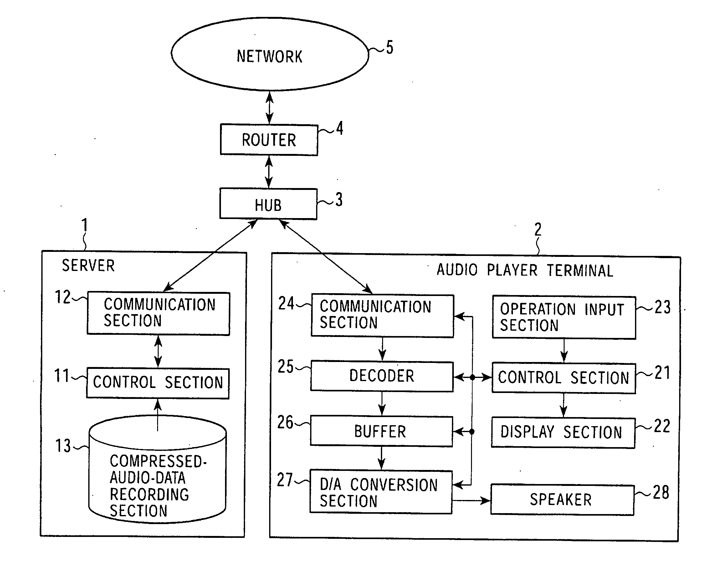
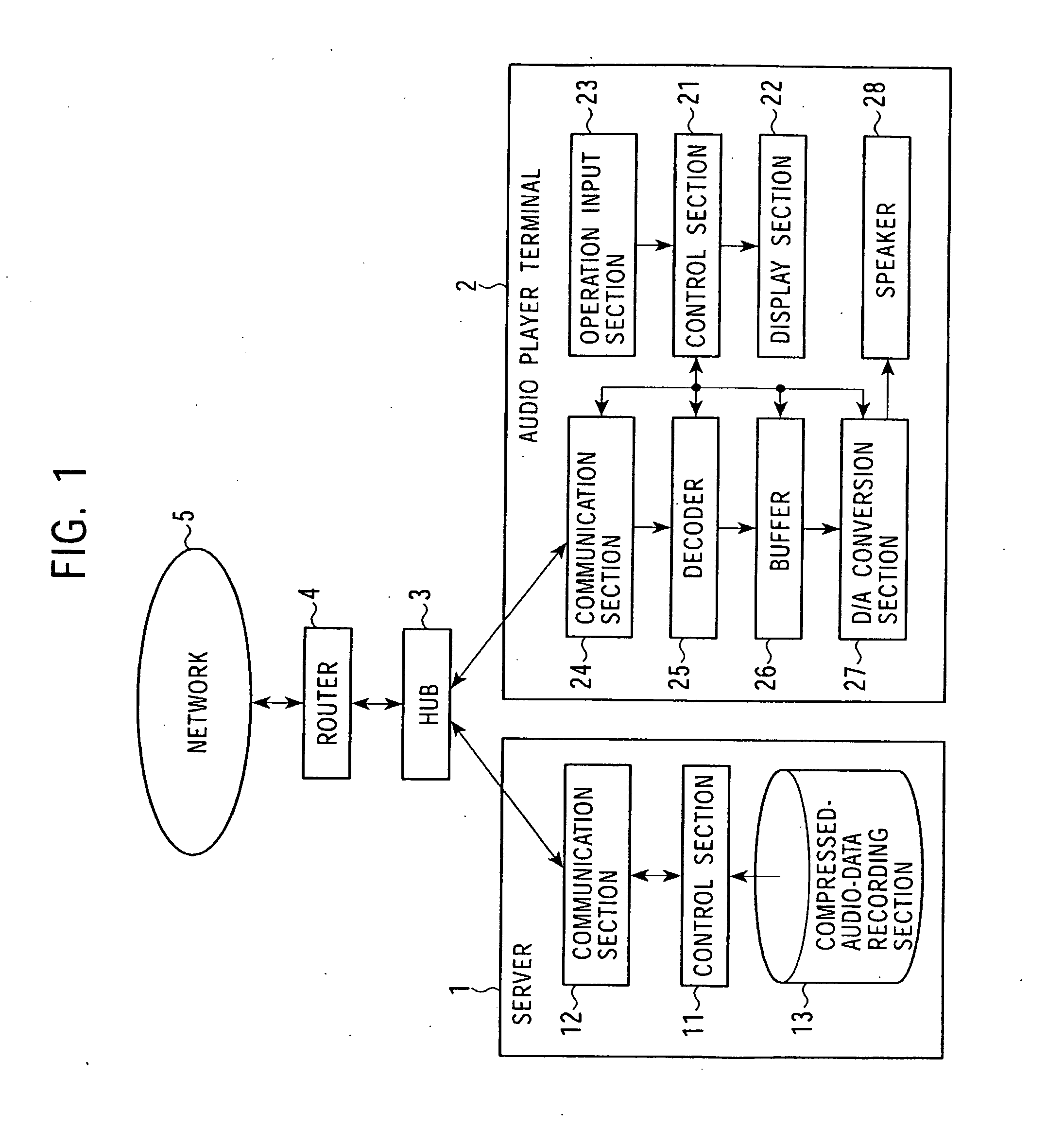
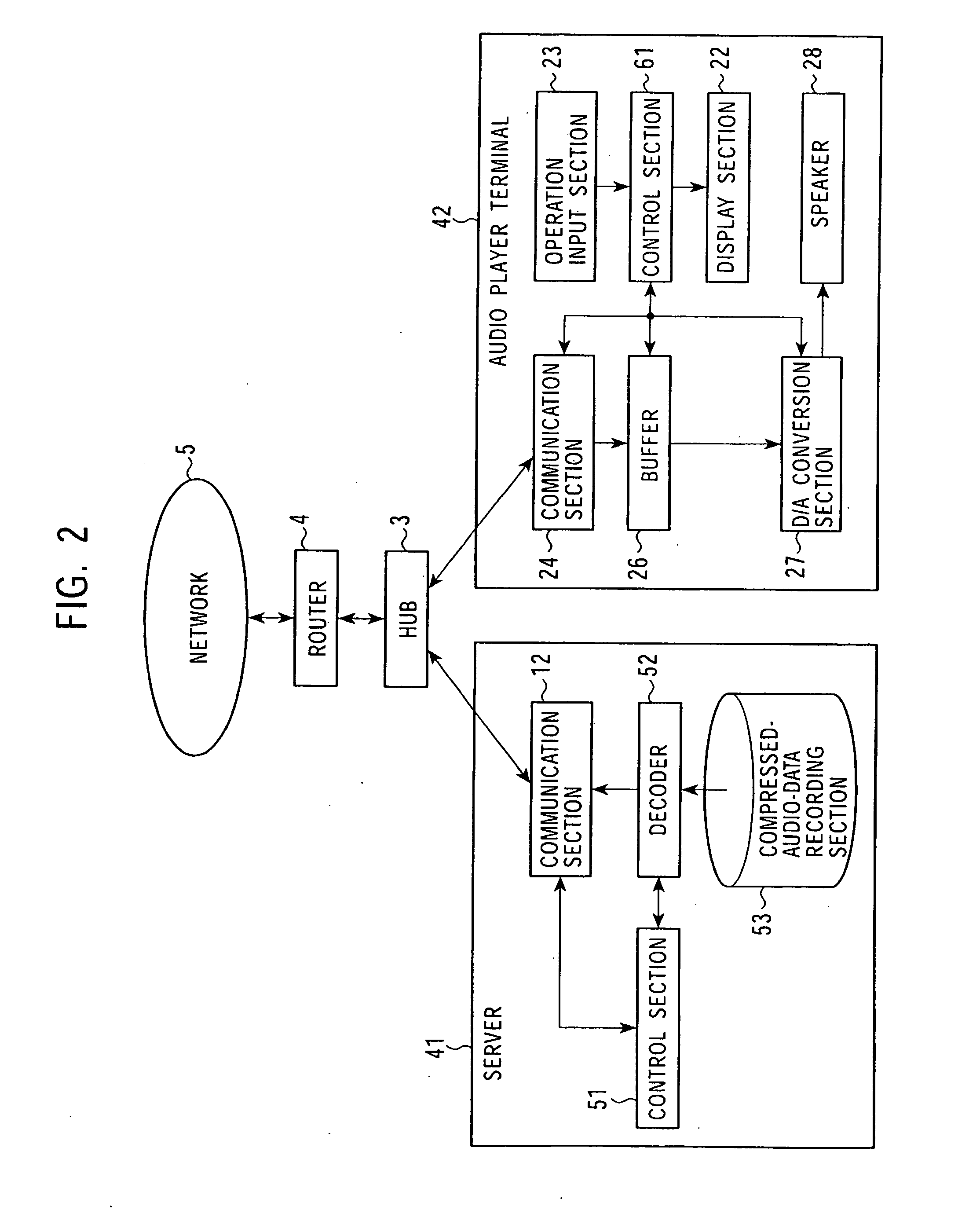
[0092]Embodiments of the present invention will be described below by referring to the drawings.

[0093]FIG. 2 is a view of a system for distributing and reproducing audio data, according to the present invention.

[0094]The same symbols as those used in the conventional case are applied to the portions corresponding to those described in the conventional case, and a description thereof is omitted.

[0095]A server 41 and an audio player (reproduction) terminal 42 are connected to a network through a hub 3. The server 41 and the audio player terminal 42 may be connected to the hub 3 by wires or by radio.

[0096]Due to the development of recent communication technologies, it is possible to transmit and receive a larger amount of data at a higher speed than before, with both wire communication and radio communication. Especially in data communications inside local area networks (LANs) configured in houses or companies, the amount of data which can be transmitted per unit time has become very l...


PUM


Abstract

A mutual recognition process is performed in step S1. When it is determined in step S2 that a request for sending a list of musical pieces has been received, the list of musical pieces is sent in step S3. When a request for sending audio data has been received in step S4, a transfer-rate measurement process is executed in step S5. When it is determined according to the transfer rate in step S6 that the audio can be transmitted, the corresponding compressed audio data is extracted in step S7, the compressed audio data is decoded to generate linear PCM data suited to the transfer rate in step S8, and transmitted in step S9. When the audio data cannot be transmitted, an error message is transmitted in step S10. The present invention can be applied, for example, to a server for distributing audio data and an audio player terminal for reproducing the distributed audio data.

Description

CROSS REFERENCES TO RELATED APPLICATIONS[0001]This application is a Continuation of U.S. application Ser. No. 10 / 382,074, filed Mar. 5, 2003, which, in turn, claims priority under 35 U.S.C. §119 to Japanese Patent Application No. JP 2002-059130, filed in the Japanese Patent Office on Mar. 5, 2003, the entire contents of which being incorporated herein by reference.BACKGROUND OF THE INVENTION[0002]1. Field of the Invention[0003]The present invention relates to information processing apparatuses, information processing terminals, information processing methods, information processing systems, recording media, and programs, and more particularly, to an information processing apparatus, an information processing terminal, an information processing method, an information processing system, a recording medium, and a program suited to a case in which data is transmitted and received through a network.[0004]2. Description of the Related Art[0005]There has been conventionally a technology in...

Claims


Application Information

Patent Timeline
Patent Type & Authority Applications(United States)
IPC IPC(8): G06F15/16G06F15/173G06F3/048G06F17/30G10K15/02G10L19/00G10L19/02H04L12/28H04L29/06
CPCH04L29/06H04L29/06027H04L65/4084H04L65/80H04L65/604H04L65/607H04L65/602H04L65/764H04L65/762H04L65/70H04L65/612H04N21/262H04L9/40H04L65/1101
Inventor YONEDA, MICHIAKIYORITATE, MASATAKA
Owner SONY CORP
Learn More