
Apparatus of cardiopulmonary resuscitator

a cardiopulmonary resuscitation and apparatus technology, applied in the field of chest compression apparatus, can solve the problems of victims dying, irreparable brain damage will be further caused, sudden cardiac death within minutes of onset, etc., and achieve the effect of reducing manufacturing cost, reducing failure risk and simplifying mechanical design

Active Publication Date: 2008-06-19
IND TECH RES INST +1
View PDF54 Cites 30 Cited by
  • Summary
  • Abstract
  • Description
  • Claims
  • Application Information

AI Technical Summary

Benefits of technology

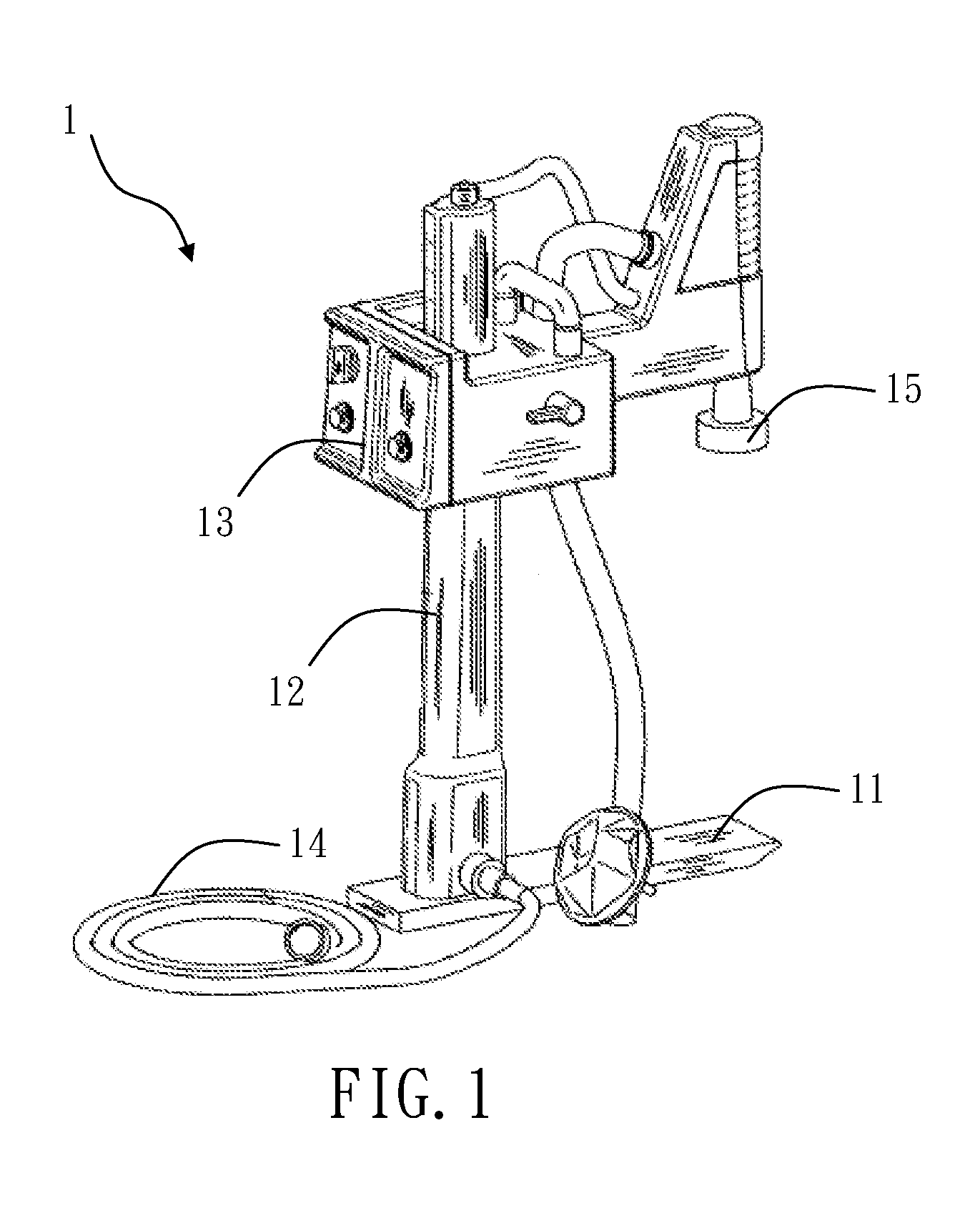
[0010]The present invention is to provide a cardiopulmonary resuscitator with a massage mechanism actuated by the pneumatic power to drive the belt around the chest of the patient so as to achieve a purpose of simplifying the mechanical design and reducing the risk of failure and cost of manufacturing.

Problems solved by technology

The American Heart Association (AHA) has estimated that over 350,000 individuals in the United States experience a sudden cardiac arrest (SCA) each year, which is a sudden, abrupt loss of heart function resulting in sudden cardiac death within minutes of onset.
Unfortunately, 95 percent of SCA victims die because cardiopulmonary resuscitation (CPR) isn't provided soon enough.
Due to brain damage is likely to occur in just 4 to 6 minutes without oxygen supplying, and irreparable brain damage will be further caused while there is no oxygen supplying in more than 6 minutes.
However, manual CPR, even operated properly, will not provide enough efficiency to maintain the normal circulation of blood flowing to brain or heart due to, during processing CPR, the effectiveness getting decreased in occasions such as inadequate chest compression, rescuer fatigue, and moving patient by rescuer.

Method used


Image

  • Apparatus of cardiopulmonary resuscitator
  • Apparatus of cardiopulmonary resuscitator
  • Apparatus of cardiopulmonary resuscitator

Examples


first embodiment

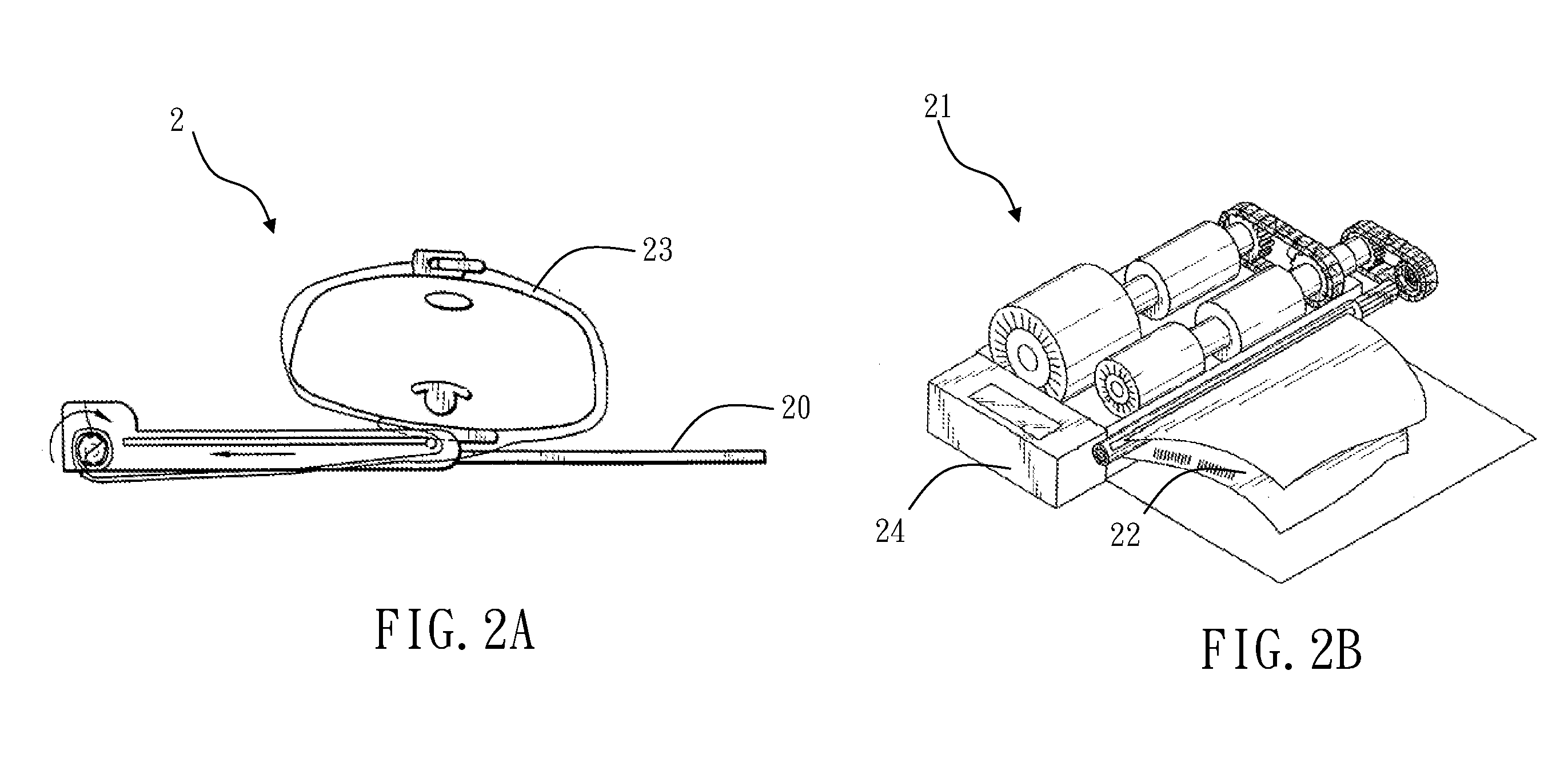
[0028]Please refer to FIG. 4A and FIG. 4B, which illustrate the operation of the cardiopulmonary resuscitator according to the present invention. The patient 90 lies down the panel 30 and the first belt 31 wraps the chest of the patient 90. By means of the controlling module controlling the pneumatic pressure inside the flexible body 37, the flexible body 37 inflates, shown in FIG. 4A, to actuate the second belt 32 pulling the first belt 31 through the buckle 33. Once the first belt 31 is pulled, the first belt 31 will tighten to compress the chest of the patient 90. Please refer toFIG. 4B, the controlling module controls the air to pass out of the flexible body 37 which deflates the flexible body 37 so that the second belt 32 returns to the original status to loosen the first belt 31 so as to release the chest of the patient 90. With the cyclically movement of the first belt 31 shown in FIG. 4A and FIG. 4B, the pressure inside the chest of the patient 90 increases to push the blood...

second embodiment

[0033]Please refer to FIGS. 6A and 6B, which illustrates cardiopulmonary resuscitator according to the present invention. In the embodiment, the cardiopulmonary resuscitator 4 comprises a panel 40, a first belt 41, and controlling module (not shown in figure) and a driving device 45. The panel 40, the first belt 41, and the controlling module are the same as the embodiment described previously.

[0034]The driving device 45 has an air cylinder 450, a piston rod 451 and a fastener 452. The air cylinder 450 actuates the piston rod 451 to generate a linear reciprocating motion through the pneumatic power from the pneumatic source 44. The fastener 452, disposed in the front end of the piston rod 451, functions to clamp a second belt 42. The two ends of the second belt 42 connect to the two ends of the first belt 41 with a buckle 43 respectively. A plurality of rollers 46, disposed on the bottom side of the panel 40, contact to the second belt for providing action force to the second belt 4...

third embodiment

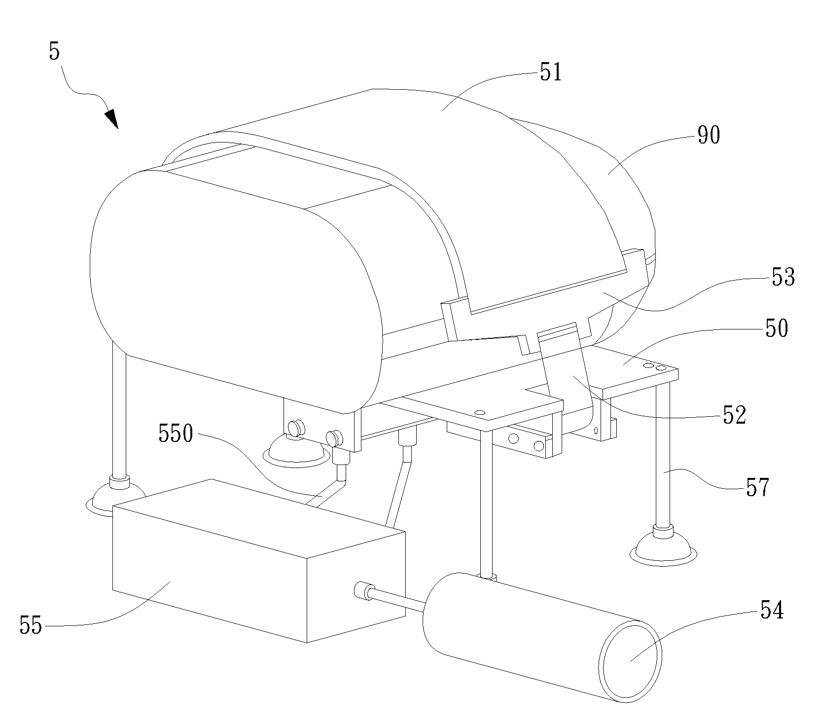
[0037]Please refer to FIG. 7A and FIG. 7B, which illustrates cardiopulmonary resuscitator according to the present invention. In this embodiment, the cardiopulmonary resuscitator 5 has a panel 50 for supporting a patient 90, a first belt 51, a controlling module 55, and a driving device 56. The panel 50 has four supporters 57 disposed at four edges of the bottom side of the panel 50. The panel 50, the first belt 51 and the controlling module 55 are the same as the embodiment described before, it will not be further described hereafter.

[0038]The driving device 56 includes an air cylinder 560, a clamping member 561, a pair of second belts 52, and a pair of holders 562. The air cylinder 560 disposed on the bottom of the panel 50 communicates with the controlling module 55 through air piping 550. The air cylinder 560 actuates a piston rod disposed thereon to generate a linear reciprocating motion through the pneumatic power from the pneumatic source 54. The clamping member 561 connects ...


PUM


Abstract

The present invention discloses an apparatus of cardiopulmonary resuscitator that is operated through a driving mechanism controlled and driven by air power. The driving mechanism functions to actuate a belt adapted to extend around the chest of a patient to generate reciprocating movement of pressing and releasing so as to achieve a purpose of cardiopulmonary resuscitation for recovering heartbeat and breathing of the patent. By means of the disclosure of the present invention, the apparatus of cardiopulmonary resuscitator is capable of being operated in any kinds of occasions without worrying about lack of power electricity. Meanwhile, the driving mechanism can provide higher reliability and lower cost through the mechanism design that is more simplified than the design of electrical control element used in the conventional apparatus.

Description

FIELD OF THE INVENTION[0001]The present invention relates to a chest compression apparatus, and relates to an apparatus of cardiopulmonary resuscitator.BACKGROUND OF THE INVENTION[0002]The American Heart Association (AHA) has estimated that over 350,000 individuals in the United States experience a sudden cardiac arrest (SCA) each year, which is a sudden, abrupt loss of heart function resulting in sudden cardiac death within minutes of onset. Unfortunately, 95 percent of SCA victims die because cardiopulmonary resuscitation (CPR) isn't provided soon enough.[0003]CPR is the abbreviation for cardio pulmonary resuscitation, and is an emergency technique applied by combining artificial respiration and massage outside the heart, when breathing stops and the heart stops beating. Due to brain damage is likely to occur in just 4 to 6 minutes without oxygen supplying, and irreparable brain damage will be further caused while there is no oxygen supplying in more than 6 minutes. Accordingly, i...

Claims


Application Information

Patent Timeline
IPC IPC(8): A61H31/00
CPCA61H31/00A61H2031/003A61H31/008A61H31/006
Inventor HO, CHAN-HSIAOCHOU, CHIH-CHUNGWU, TENG-CHUNCHUANG, BOR-NIANCHEN, SHING
Owner IND TECH RES INST
Learn More