Optical signal noise suppressor and optical signal noise suppressing method
a technology of optical signal and suppressor, applied in the field of optical signal noise suppressor, can solve the problem of reducing the quality of signal light, and achieve the effect of reducing the noise components
- Summary
- Abstract
- Description
- Claims
- Application Information
AI Technical Summary
Benefits of technology
Problems solved by technology
Method used
Image
Examples
first embodiment
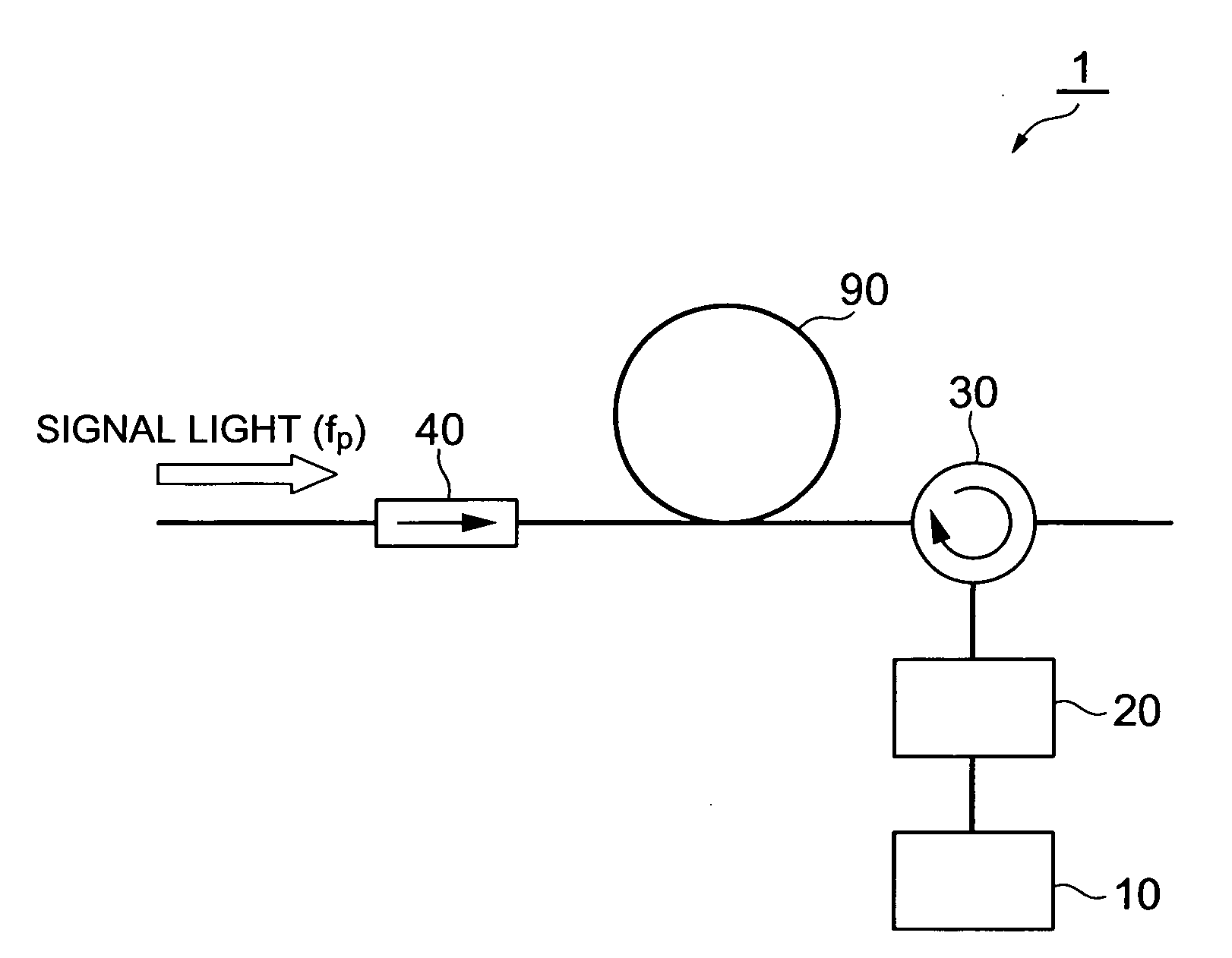
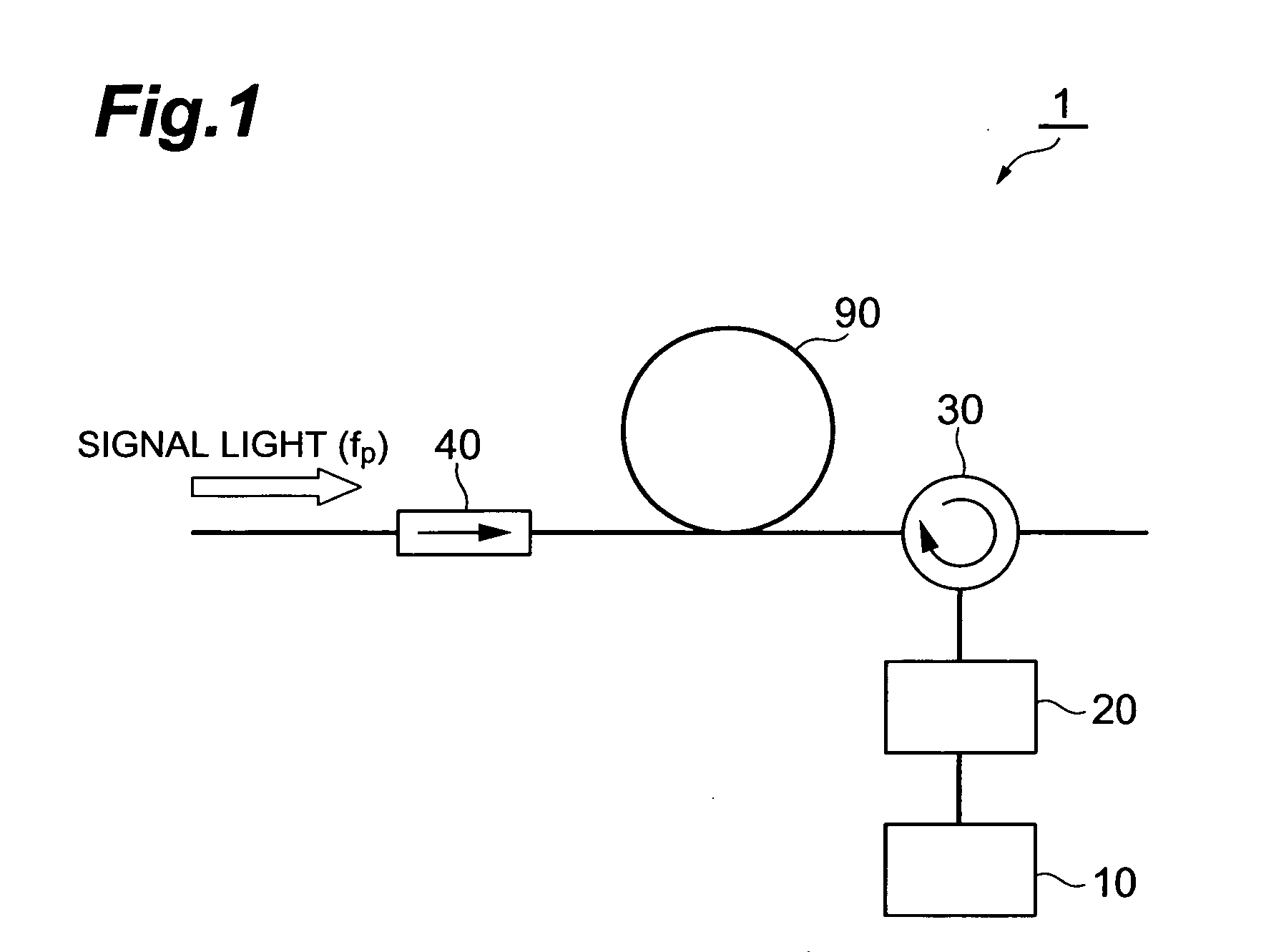
[0024]A first embodiment of the optical signal noise suppressor and the optical signal noise suppressing method is described first. FIG. 1 is a view showing a configuration of a first embodiment of an optical signal noise suppressor according to the present invention. The optical signal noise suppressor 1 according to the first embodiment, shown in FIG. 1, is a device for suppressing noise caused by stimulated Brillouin scattering (SBS), which is generated when a signal light propagates in an optical fiber 90 from a first end side to a second end side, and comprises a light source section 10, optical attenuator 20, optical circulator (first coupler) 30 and an optical isolator (interruption section) 40.
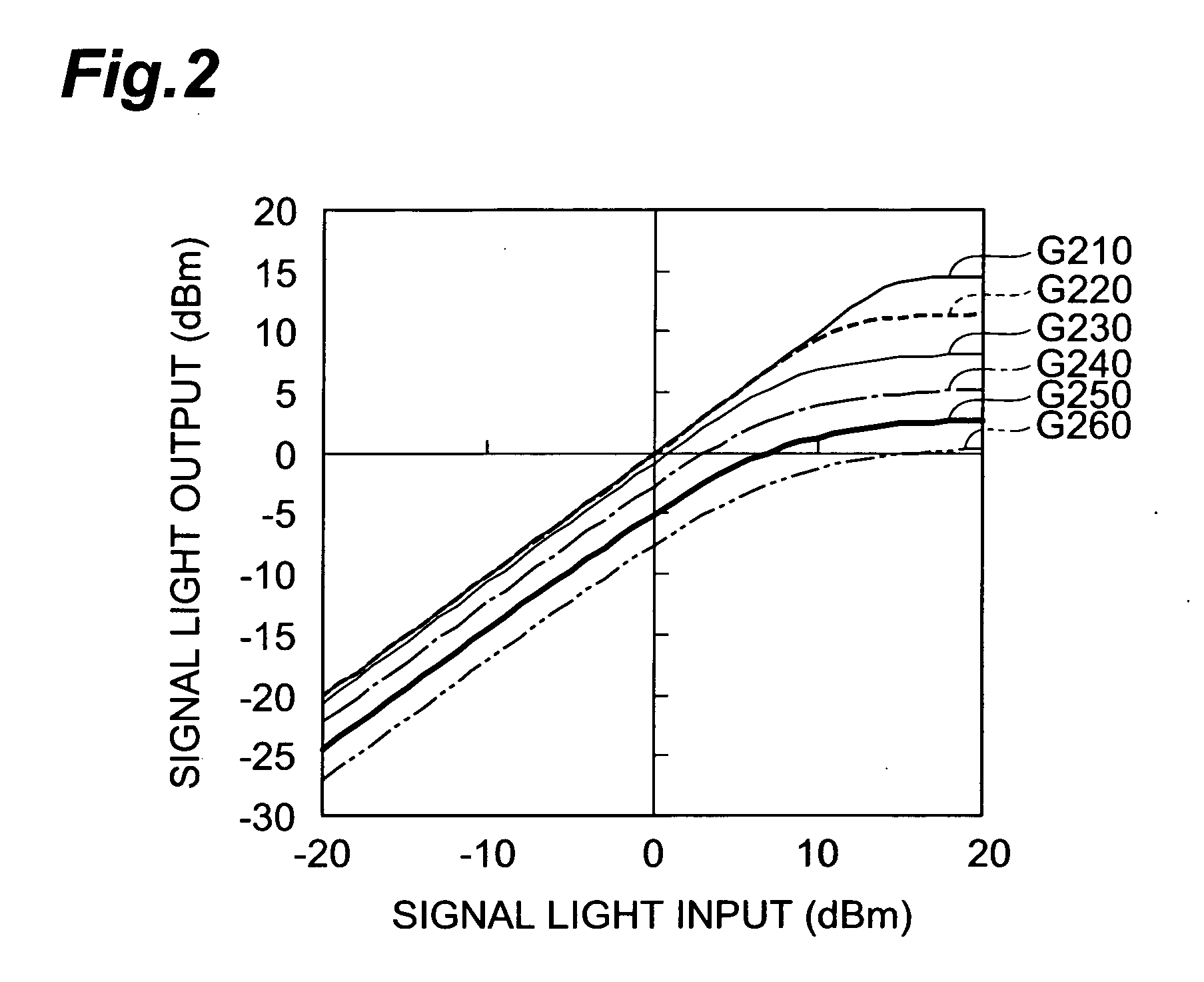
[0025]In an optical fiber 90, the signal light propagates from the optical isolator 40 to the optical circulator 30. A single optical frequency or a plurality of optical frequencies may be used for the signal light. A single optical frequency is for the case of performing signal proces...
second embodiment
[0035]Next, a second embodiment of the optical signal noise suppressor and the optical signal noise suppressing method according to the present invention will be explained. FIG. 3 is a view showing a configuration of a second embodiment of an optical signal noise suppressor according to the present invention. The difference here from the configuration of the first embodiment shown in FIG. 1 is that the optical signal noise suppressor 2 of the second embodiment in FIG. 3 has a pumping light source section 10A, instead of the pumping light source section 10. In the second embodiment as well, an optical attenuator 20 may be provided between the pumping light source section 10A and an optical circulator 30.
[0036]The pumping light source section 10A includes a pumping light source 11 and a highly nonlinear optical fiber 12. In the pumping light source section 10A, the light which was outputted from the pumping light source 11 is inputted to the highly nonlinear optical fiber 12, and band...
third embodiment
[0038]Next, a third embodiment of the optical signal noise suppressor and the optical signal noise suppressing method according to the present invention will be explained. FIG. 4 is a view showing a configuration of a third embodiment of an optical signal noise suppressor according to the present invention. The difference here from the configuration of the first embodiment in FIG. 1 is that the optical signal noise suppressor 3 of the third embodiment in FIG. 4 has a pumping light source section 10B, instead of the pumping light source section 10. In the third embodiment as well, an optical attenuator 20 may be provided between the pumping light source section 10B and an optical circulator 30.
[0039]The pumping light source section 10B includes a pumping light source 11, a phase modulator 13 and a tone signal generator 14. In the pumping light source section 10B, a tone signal, which is outputted from the tone signal generator 14, is inputted to the phase modulator 13, and light, whi...
PUM
| Property | Measurement | Unit |
|---|---|---|
| length | aaaaa | aaaaa |
| length | aaaaa | aaaaa |
| length | aaaaa | aaaaa |
Abstract
Description
Claims
Application Information
 - R&D
- Intellectual Property
- Life Sciences
- Materials
- Tech Scout
- Unparalleled Data Quality
- Higher Quality Content
- 60% Fewer Hallucinations
Browse by: Latest US Patents, China's latest patents, Technical Efficacy Thesaurus, Application Domain, Technology Topic, Popular Technical Reports.
© 2025 PatSnap. All rights reserved.Legal|Privacy policy|Modern Slavery Act Transparency Statement|Sitemap|About US| Contact US: help@patsnap.com


