
Heat exchanger for a vehicle

Inactive Publication Date: 2008-06-19
HANON SYST
View PDF13 Cites 8 Cited by
  • Summary
  • Abstract
  • Description
  • Claims
  • Application Information

AI Technical Summary

Benefits of technology

[0009]It is an object of the present invention to provide a heat exchanger, i.e., a highly efficient thin radiator for reducing production costs by decreasing the weight of a heat exchanger, reducing energy loss due to a pressure drop of a coolant-side in a case of being mounted in a real vehicle, and enhancing heat radiation performance.
[0010]It is another object of the present invention to provide an optimal design condition for enhancing heat radiation performance of a radiator in a coolant flow rate region corresponding to a hill-climbing mode that is a critical driving mode of a vehicle and reducing a coolant-side pressure drop amount.
[0011]It is a further object of the present invention to provide a preferred a design condition of a lightweight thin radiator, wherein heat radiation performance of a conventional radiator with a broad width and a heavy weight can be maintained, and a coolant-side pressure drop amount almost identical with that of the conventional radiator can also be maintained when comparing the heat radiation performance and coolant-side pressure drop amount of the conventional radiator.
[0012]It is a still further object of the present invention to provide a preferred design range of each main component of the radiator, which can meet the optimal design range.
[0017]Preferably, Tth the material thickness of the tube is in the range of 0.15 to 0.24 mm for the purpose of reducing a weight and a pressure drop amount.
[0018]Preferably, Fh the height of the fin is in the range of 5.3 to 5.8 mm, and the thickness of the fin is in the range of 0.05 to 0.06 mm for the purpose of reducing a weight and maximizing a heat transfer rate.

Problems solved by technology

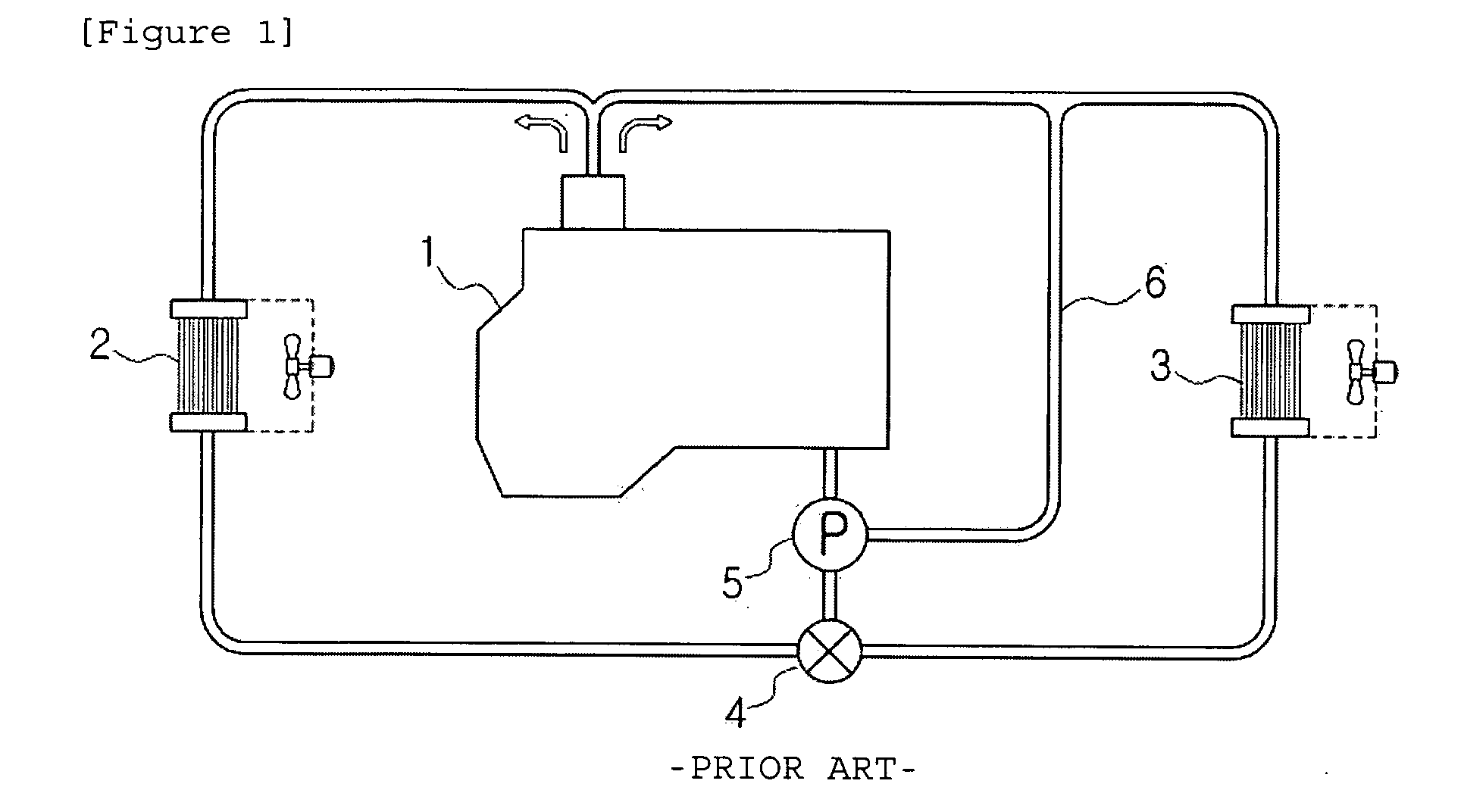
Since an engine 1 for a vehicle always ignites and burns high-temperature and high-pressure gas, the engine 1 is overheated in a case where it is left as it is, so that cylinders and pistons may be seriously damaged due to the melt of a metallic material constituting the engine 1.
However, if the height of the fin becomes too low, a foreign substance is stuck or stacked between the fins so that it interferes with ventilation, and since a foreign substance produced due to an antifreezing solution or a reactant is stacked inside the tube if the height of the tube becomes too small, there occurs a phenomenon in that a flow channel is blocked so that the deterioration of heat transfer performance may be rather caused.
In this case, since the number of tubes and fins become large, there may be caused a problem in that this is very disadvantageous in a view of stability of a radiator structure and productivity in manufacturing.
Further, there is no detailed understanding of an effect of pressure loss due to surface shear stress occurring on a wall surface of the tube, which is accompanied in a case where the flow of a coolant in the heat exchange tube is developed into a turbulent flow region.
Particularly, there are some limitations in suggesting a preferred design object of exchanger tubes in a critical operation condition such as alpine regions with many inclines or cold or arctic regions.

Method used


Image

  • Heat exchanger for a vehicle
  • Heat exchanger for a vehicle
  • Heat exchanger for a vehicle

Examples


Embodiment Construction

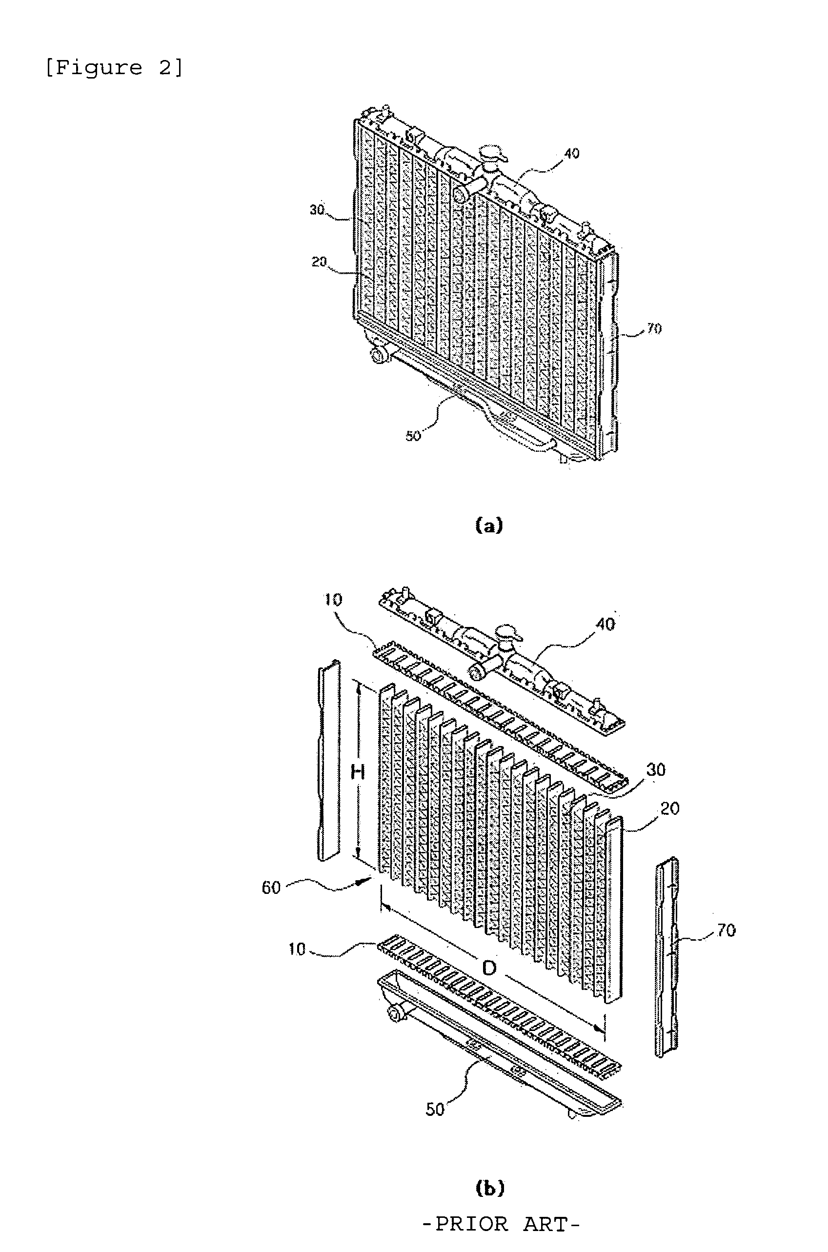
[0028]10: Header

[0029]20: Heat exchanging tube

[0030]30: Fin

[0031]40, 50: Tank

[0032]60: Core portion

[0033]70: Support

BEST MODE FOR CARRYING OUT THE INVENTION

[0034]Practical and presently preferred embodiments of the present invention are illustrative as shown in the following Examples and Comparative Examples.

[0035]However, it will be appreciated that those skilled in the art, on consideration of this disclosure, may make modifications and improvements within the spirit and scope of the present invention.

[0036]In a case of a radiator, although a heat transfer rate by air-side heat conduction occupies the largest portion of the heat transfer rate by heat transfer, variation of a heat radiation characteristic in accordance with structure modification of a component of the radiator is not so large. On the other hand, although a heat transfer rate by heat conduction in a heat exchange tube, which is a high temperature side, is low at a rate occupying in the entire heat transfer rate, a c...


PUM


Abstract

A heat exchanger for a vehicle engine includes a pair of tanks for supplying a coolant through a thermostat for adjusting opening / shutting depending on the temperature of the coolant and a water pump, and discharging the cooled coolant to an engine side; a header at one side coupled with the tank at one side, to which the coolant is supplied; heat exchange tubes which are structurally fastened to communicate with the heater at one end portion thereof, and arranged in parallel to a direction of driving wind; a header at the other side coupled with the tank at the other side, which is structurally fastened at the other end portion of the heat exchange tube to communicate therewith so as to discharge the coolant into the engine; and a core portion including fins fixedly brazed between the heat exchange tubes.

Description

TECHNICAL FIELD[0001]The present invention relates to a heat exchanger for a vehicle, and more particularly, to a highly efficient thin radiator for reducing production costs by decreasing the weight of a heat exchanger, reducing energy loss due to a pressure drop of a coolant-side in a case of being mounted in a real vehicle, and enhancing heat radiation performance.BACKGROUND ART[0002]FIG. 1 is a conceptual view showing a cooling system of a general vehicle. Since an engine 1 for a vehicle always ignites and burns high-temperature and high-pressure gas, the engine 1 is overheated in a case where it is left as it is, so that cylinders and pistons may be seriously damaged due to the melt of a metallic material constituting the engine 1. In order to prevent this, as shown in FIG. 1, a water jacket (not shown), in which a coolant is stored, is mounted around the cylinder of the engine 1 for a vehicle, the engine is circularly cooled by allowing the coolant to pass through a radiator 2...

Claims


Application Information

Patent Timeline
IPC IPC(8): F28F13/00
CPCF01P7/164F28D2021/0094F28D1/05366F01P2003/001F28F9/013F28F9/00F28F9/04
Inventor CHANG, SIM HOAN, JEONG SUNWOONG, JUN GILSUN, CHO BYOUNGYUL, LEE SANGYONG, JUNG KWANG
Owner HANON SYST
Learn More