
Systems and Arrangements for Clock and Data Recovery in Communications

a clock and data recovery technology, applied in the field of communication systems, can solve the problems of consuming a significant amount of power, further occupying significant and valuable space on an integrated circuit, and a topology-based way to recover such data, and achieves acceptable bit error rates and low power operation.

Inactive Publication Date: 2008-06-12
GLOBALFOUNDRIES INC
View PDF13 Cites 45 Cited by
  • Summary
  • Abstract
  • Description
  • Claims
  • Application Information

AI Technical Summary

Benefits of technology

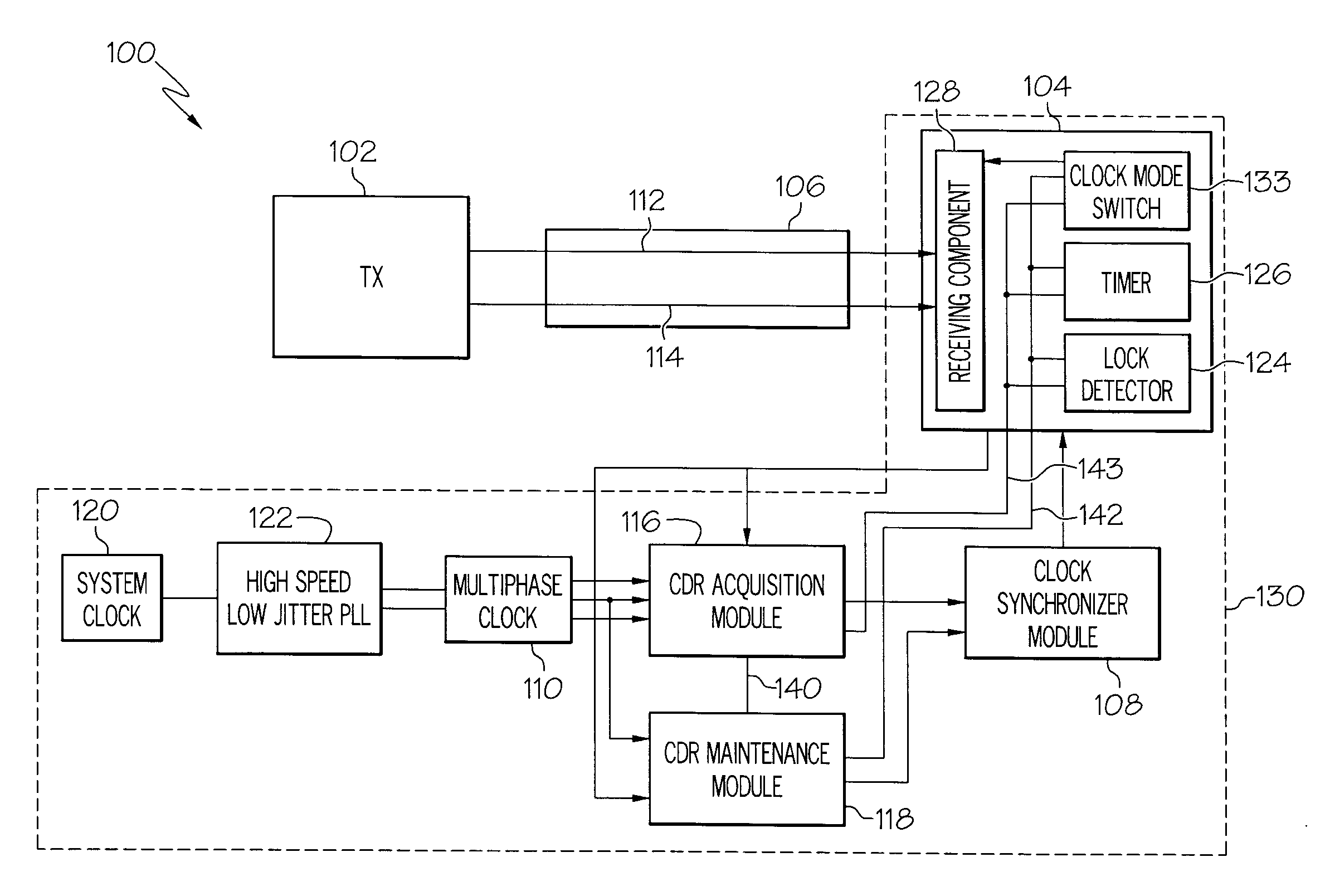
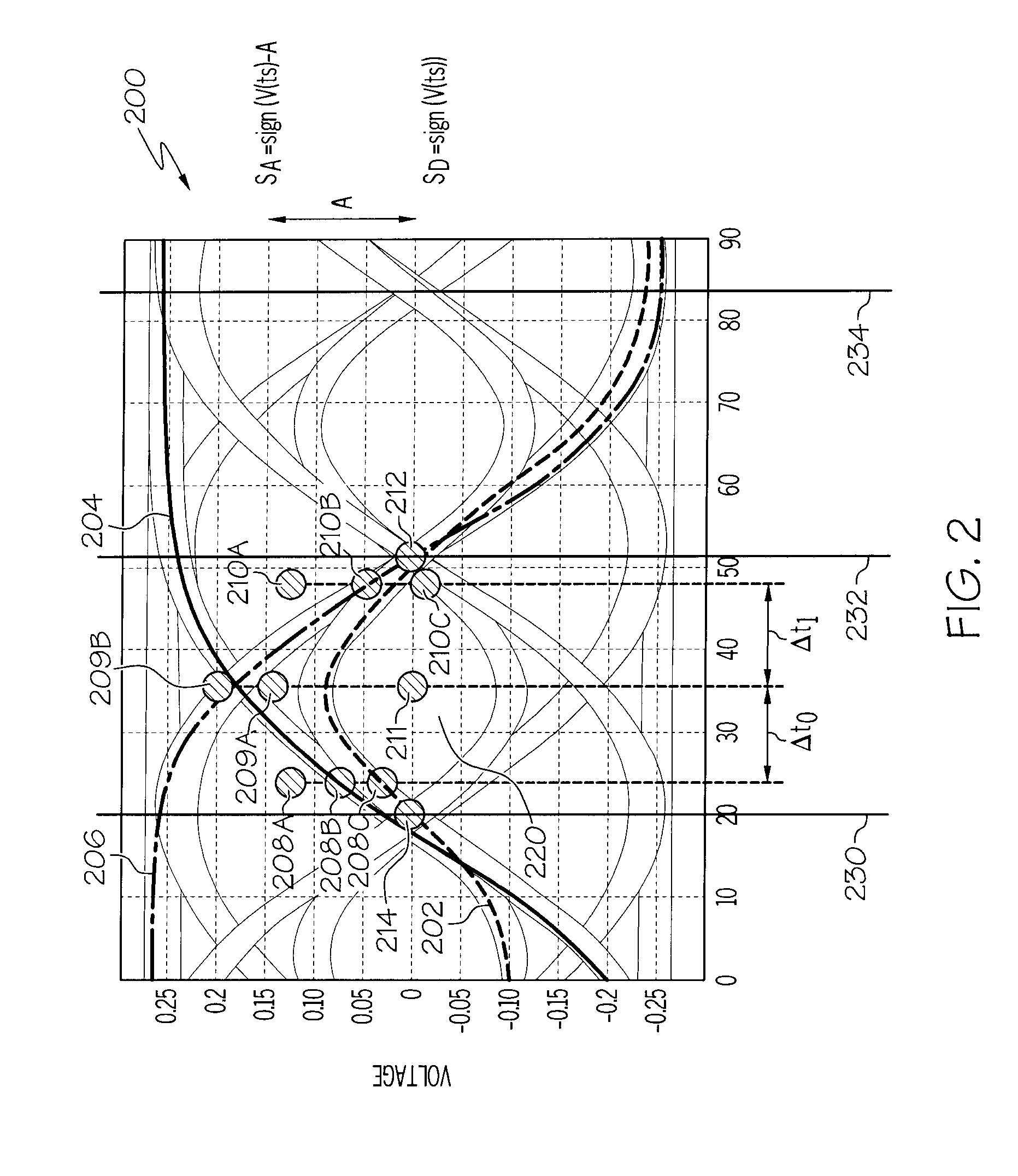
[0019]Once the CDR acquisition module, acting with or without the assistance of a secondary frequency acquisition loop, has enabled the dual mode system to come within a predetermined data reception performance specification (referred to herein as a data lock), operation of the dual mode system can change from the acquisition mode to the low power maintenance mode. The low power maintenance mode can utilize a single clock with a feedback loop to adjust the timing of the data acquisition clock. The feedback can be based on trends of the incoming waveform such that fine tuning of the timing of the data acquisition clock can be achieved. Such a trend based timing control system can achieve equivalent or improved data error rates over traditional CDR systems utilizing a fraction of the power required by the traditional CDR systems.
[0024]The sampling of the data waveform with the multiphase clock-clock acquisition module can quickly provide a data acquisition clock so that the data sample acquisition clock signal is centered within the bit cycle. The CDR system can then reconstruct the data stream on the transmission line. After some reconstructed data is acquired, the single clock module can synchronized with the incoming data stream based on a timing signal possibly from the data acquisition clock of the multiphase clock. In a low power maintenance mode, a single clock from a single clock module can be utilized to sample the data waveform and to provide the data acquisition clock to the receiver. The single clock can continuously fine tune the data acquisition sampling position while maintaining lower power operation so that acceptable bit error rates can still be achieved.
[0026]Accordingly, the above disclosed dual mode low power clock system can be utilized by a CDR system to acquire clock and data timing over a communication link and to adjust the timing of a sample clock such that the bit error rate of a communication system will remain low when in a low power consumption mode. The multi-clock mode can have a low duty cycle or “active” period such that the system disclosed can consume less clock power than that required by traditional CDR systems. Additionally, a low overall system bit error rates are preserved.

Problems solved by technology

It can be appreciated that while the traditional oversampling topology in CDR systems is an effective way to recover data on a serial communication line, such a topology can be a costly and inefficient way to recover such data.
Specifically, many CDR systems are typically required in a single integrated circuit system and each clock and associated clock distribution network required in such oversampling circuits typically consume a significant amount of power and further take up significant and valuable space on an integrated circuit.
Although the frequency of the sampling clock can be set based on the frequency of the transmitter clock, unknown delays can occur between the transmitter and the receiver.
In addition, the timing of the received waveform can undergo random changes, known as timing jitter, which are induced by non-idealities of the clock circuitries and the transmission path.
Furthermore, the presence of even small offsets between transmitter and receiver base frequencies will result in continuous changes in the relative phase between transmit and receive clock signals.
As stated above, virtually all of these designs have multiple system clocks and other control circuitry and such systems draw a significant amount of power and take up a lot of valuable space on an integrated circuit.
Although these configurations do improve bit error rates, the penalty paid in power and size to realize the benefits provided by such circuits can be considerable.
More particularly, clock circuits utilized in data receiving circuits are very “power hungry” because they typically have the highest operating frequency in a specific circuit.
Furthermore, the distribution of such high frequency clocks from, for example, a central clock generator to the receiver macro where the clocks are used, also demands significant power.
CDR systems with reduced clock hardware can require significantly longer data acquisition times on power up and such systems can easily loose a data lock when noise, timing and other aberrations are present on the data line.
Generally, such low power designs have a greatly reduced tracking capability for the initial timing and for changes in timing of the of the incoming data waveform.
The unreliability, limited acquisition bandwidth and limited tracking bandwidth and general instability of such low power clock systems have kept such low power designs from becoming an acceptable solution to traditional CDR systems.
Increasing the accuracy of CDR amidst noise and distortions often present on a transmission line is a formidable task because the time intervals between signal transitions can become very small, demanding extreme precision of the data acquisition clock.
As stated above, clock generation and distribution in CDR circuits is one of the biggest contributors to power consumption.

Method used


Image

  • Systems and Arrangements for Clock and Data Recovery in Communications
  • Systems and Arrangements for Clock and Data Recovery in Communications
  • Systems and Arrangements for Clock and Data Recovery in Communications

Examples


Embodiment Construction

[0032]The following is a detailed description of embodiments of the disclosure depicted in the accompanying drawings. The embodiments are in such detail as to clearly communicate the disclosure. However, the amount of detail offered is not intended to limit the anticipated variations of embodiments; on the contrary, the intention is to cover all modifications, equivalents, and alternatives falling within the spirit and scope of the present disclosure as defined by the appended claims. The descriptions below are designed to make such embodiments obvious to a person of ordinary skill in the art.

[0033]While specific embodiments will be described below with reference to particular configurations of hardware and / or software, those of skill in the art will realize that embodiments of the present invention may advantageously be implemented with other equivalent hardware and / or software systems. Aspects of the disclosure described herein may be stored or distributed on computer-readable med...


PUM


Abstract

A dual mode clock and data recovery (CDR) system is disclosed. A fast locking, oversampling CDR acquisition module can begin the process to quickly create a data acquisition clock signal in start up data acquisition conditions. When at least some data can be extracted from the incoming data stream, the DRR system can indicate such stability and switch to accept control from a low power CDR maintenance module. The low power CDR maintenance module can then fine tune and maintain the timing of the data acquisition signal. If the quality of the data lock under CDR maintenance module control degrades to a sufficient degree, the high power CDR acquisition module can be re-enables and re-assert control from the low power module until such time as the lock quality is again sufficient for the low power module to be used.

Description

FIELD OF INVENTION[0001]The present disclosure is in the field of communications systems and more particularly in the field of clock and data recovery systems.BACKGROUND[0002]Communication systems typically utilize some form of clock system to synchronize communications between a transmitter and a receiver. In digital communication systems, the receiver typically operates at or near the same average frequency as the transmitting end to prevent loss of information. When digital signals are transported over a network of digital communication links, switching nodes, multiplexers, and transmission line interfaces, the task of keeping all the entities operating at the same average frequency is referred to as network synchronization.[0003]Generally, in gigabit / second communication systems it is important that a receiver reads or samples the data waveform at an appropriate point in time relative to data waveform transitions. Many techniques can be utilized to determine when to sample the d...

Claims


Application Information

Patent Timeline
IPC IPC(8): H04L7/00
CPCH04L7/0334H04L7/0004
Inventor CRANFORD, HAYDEN C.FRIEDMAN, DANIEL J.MEGHELLI, MOUNIRTOIFL, THOMAS H.
Owner GLOBALFOUNDRIES INC
Learn More