
Process for converting biogas to a pipeline grade renewable natural gas

a technology of renewable natural gas and biogas, which is applied in the field of process for converting biogas to pipeline grade renewable natural gas, can solve the problems that economic optimization cannot be achieved, and achieve the effect of reducing biogas pressure and water flow

Inactive Publication Date: 2008-06-12
FUNK MICHAEL N
View PDF5 Cites 55 Cited by
  • Summary
  • Abstract
  • Description
  • Claims
  • Application Information

AI Technical Summary

Benefits of technology

[0012]The invention provides a method of purifying low pressure biogas streams to pipeline grade methane or D.O.T. specification, or other predetermined specification, gas. The scrubbing methodology employed is unique due to the system's ability to recycle the scrubbing water and be deployed in areas where extreme weather conditions and restricted water availability do not alter the system's ability to produce a specified gas. Through controlling the scrubbing water temperature, the system is able to minimize biogas pressures and water flows generally employed by other scrubbing systems.
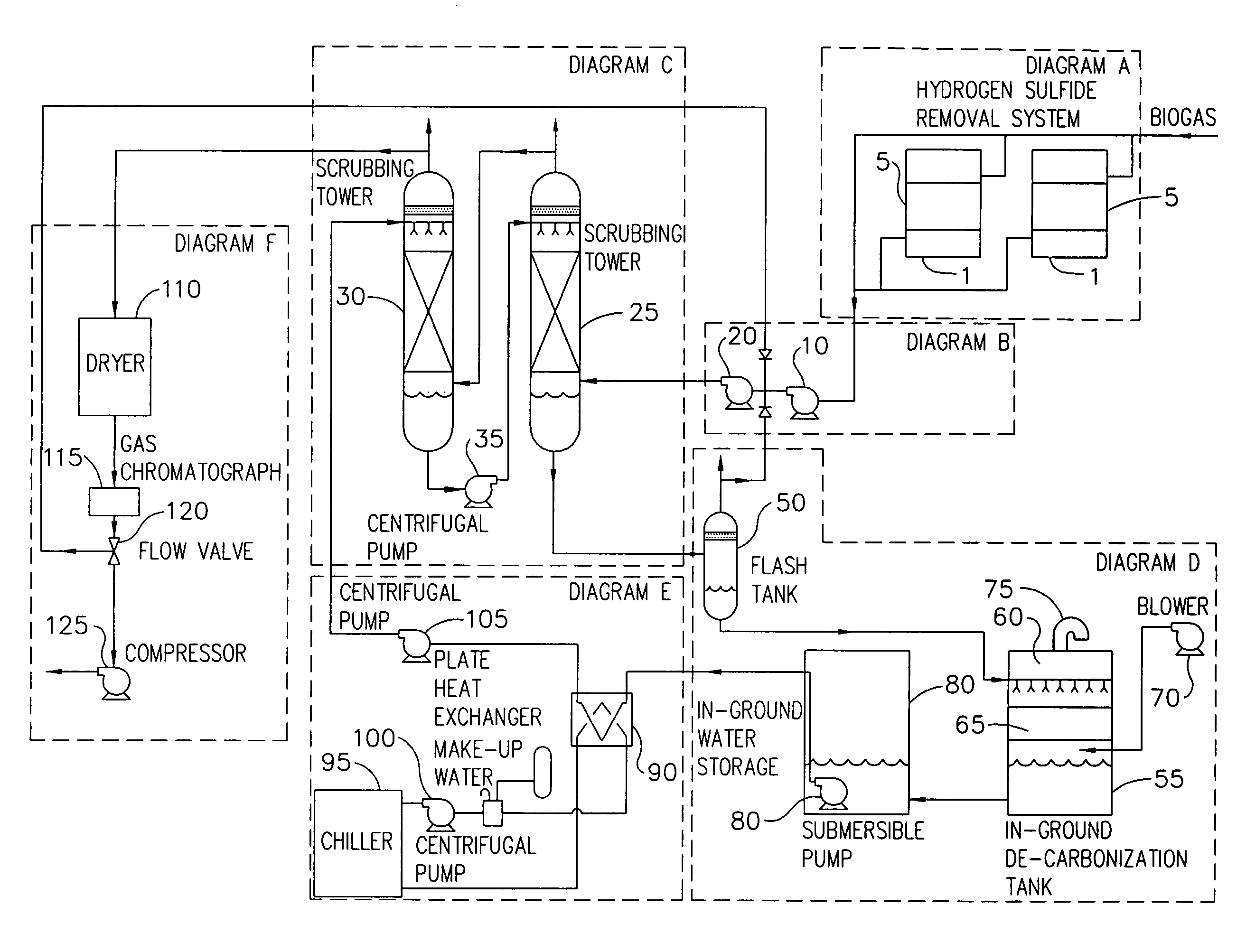
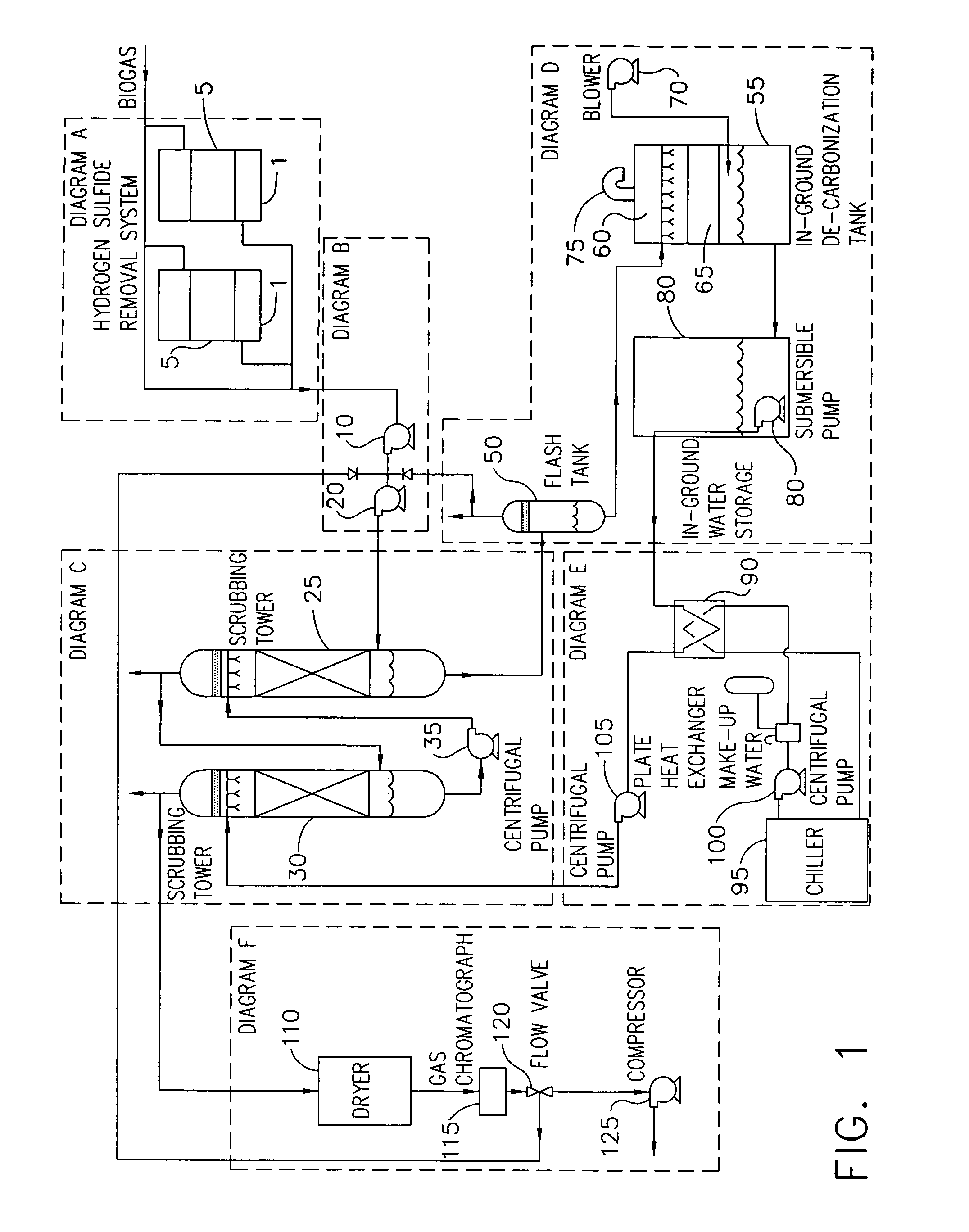
[0020]vi. As the water is recycled it first goes into an in-ground de-carbonization tank. The water is forced through a spray bar that is located above the packing. The spray bar helps achieve de-carbonization by reducing water droplet size and evenly distributing the water over the packing while air is being forced up through the packing to help release the absorbed carbon dioxide.

Problems solved by technology

Thus, without controlling the water temperature, economic optimization cannot be achieved.vi.

Method used


Image

  • Process for converting biogas to a pipeline grade renewable natural gas
  • Process for converting biogas to a pipeline grade renewable natural gas
  • Process for converting biogas to a pipeline grade renewable natural gas

Examples


Embodiment Construction

[0031]An embodiment of the present invention, depicted in FIG. 1, will be described below in further detail by reviewing each of the individual portions of that embodiment, depicted in FIGS. 2-7.

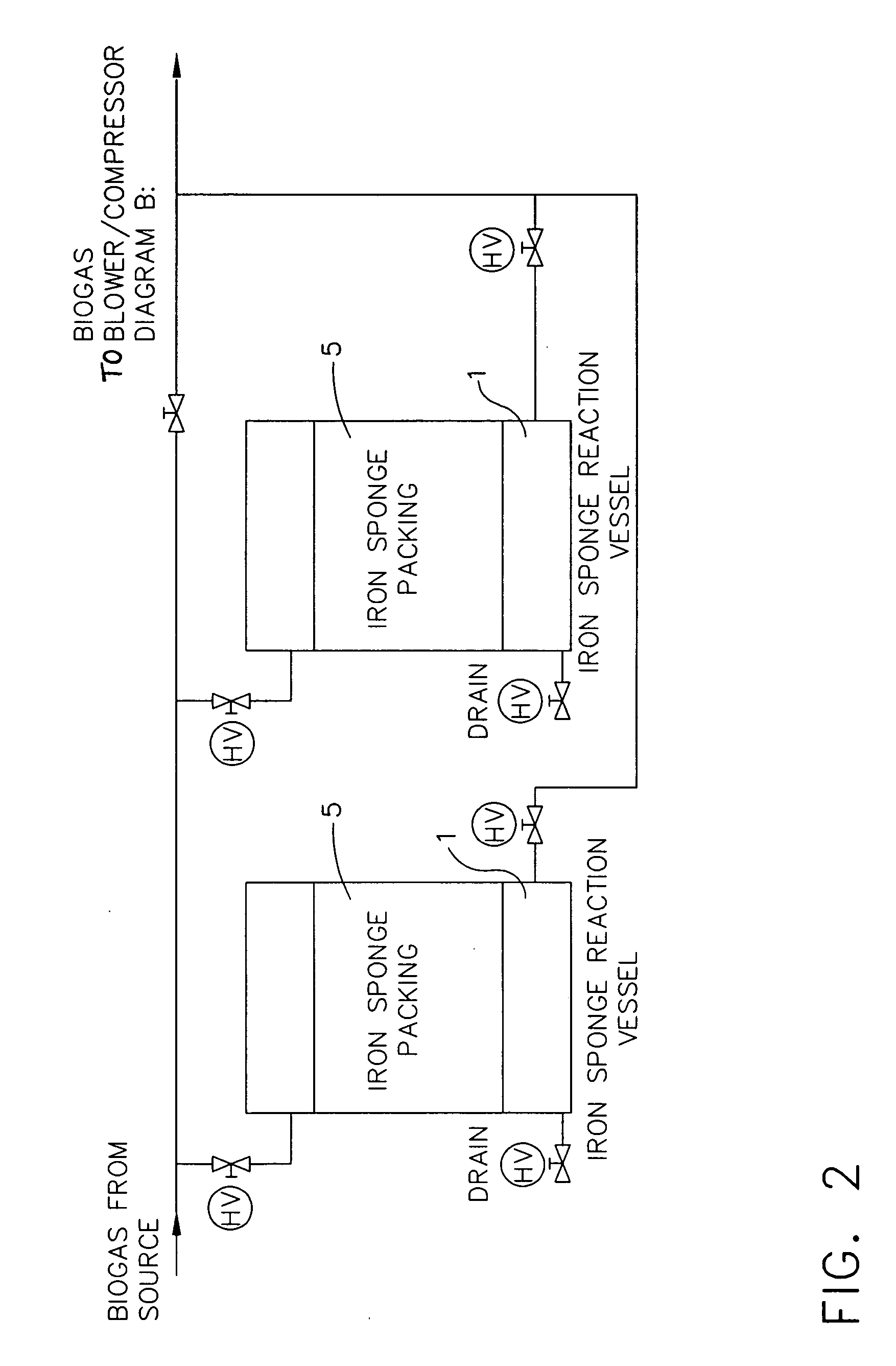
[0032]Diagram A: Dual Iron Sponge Reaction Vessels

[0033]As shown in FIG. 2, the dual iron sponge vessels (1) are used to remove the hydrogen sulfide prior to the biogas entering the absorption scrubbing process. Duplicity is not necessary but allows for the recharging of one unit while the other continues to remove hydrogen sulfide. Only one unit is active at all times. The low pressure gas stream from the anaerobic digestion source is pulled through the iron sponge vessel by fan (10). As the gas migrates down through the iron sponge vessel, the hydrogen sulfide comes into contact with iron oxide impregnated wood chips that make up the iron sponge packing (5). As the hydrogen sulfide comes into contact with the iron oxide, the reaction produces iron sulfide and water which remains in the Iro...


PUM

PropertyMeasurementUnit
Temperatureaaaaaaaaaa
Pressureaaaaaaaaaa
Contentaaaaaaaaaa

Abstract

A process purifies raw biogas created from a renewable source into pipeline grade natural gas and / or D.O.T. specification, or other predetermined specification, gas. The automated scrubbing processed employed and the particular attributes of the system allow the system to function under extreme weather conditions by employing specific tools to control the temperature of the scrubbing water to allow for efficient and effective removal of the carbon dioxide gas. The system also employs specific measures to use recycled scrubbing water, thus eliminating the need for excessive water generally needed to economically employ this type of scrubbing process. The recycled water is continuously de-carbonated to allow the recycled water stream to effectively scrub the raw biogas. Treated gas from the process is then dried, and compressed for introduction into storage tanks or a natural gas pipeline delivery system.

Description

[0001]This application claims the benefit of U.S. Provisional Application No. 60 / 874,120, entitled Process for Converting Biogas to a Pipeline Grade Renewable Natural Gas, filed Dec. 11, 2006.BACKGROUND OF THE INVENTION[0002]The present invention relates in general to employing all of the necessary elements into a scrubbing process that will allow for the economic optimization of producing pipeline grade methane or a gas that meets D.O.T. specification, for example, from biogas.[0003]Biogas can be derived from a number of different sources. The predominate sources of economically viable streams of biogas are generally produced through anaerobic digestion. Anaerobic digestion can occur naturally in landfills or in controlled environments that enhance the biological degradation of sewage waste, foodstuff waste, and animal waste.[0004]Biogas in general is a low Btu gas that is contaminated with hydrogen sulfide and carbon dioxide. The gas is also highly saturated with water.[0005]Based...

Claims


Application Information

Patent Timeline
IPC IPC(8): G01N30/04B01D46/46B01D53/14
CPCB01D53/1475B01D53/52B01D2251/602B01D2257/304B01D2257/504B01D2257/80C12M47/18C10L3/10C10L3/102G01N2030/8854G01N2030/8886Y02C10/06B01D2258/05Y02P20/59Y02C20/40
Inventor FUNK, MICHAEL N.
Owner FUNK MICHAEL N
Learn More