
Apparatus for controlling timings of intervals in which combustion chamber pressure data are acquired from output signals of cylinder pressure sensors of multi-cylinder internal combustion engine

Active Publication Date: 2008-06-05
DENSO CORP
View PDF11 Cites 10 Cited by
  • Summary
  • Abstract
  • Description
  • Claims
  • Application Information

AI Technical Summary

Benefits of technology

[0015]Hence it is a basic advantage of the invention that more effective monitoring of the combustion conditions within the engine combustion chambers can be achieved, for an internal combustion engine having a large number of cylinders.
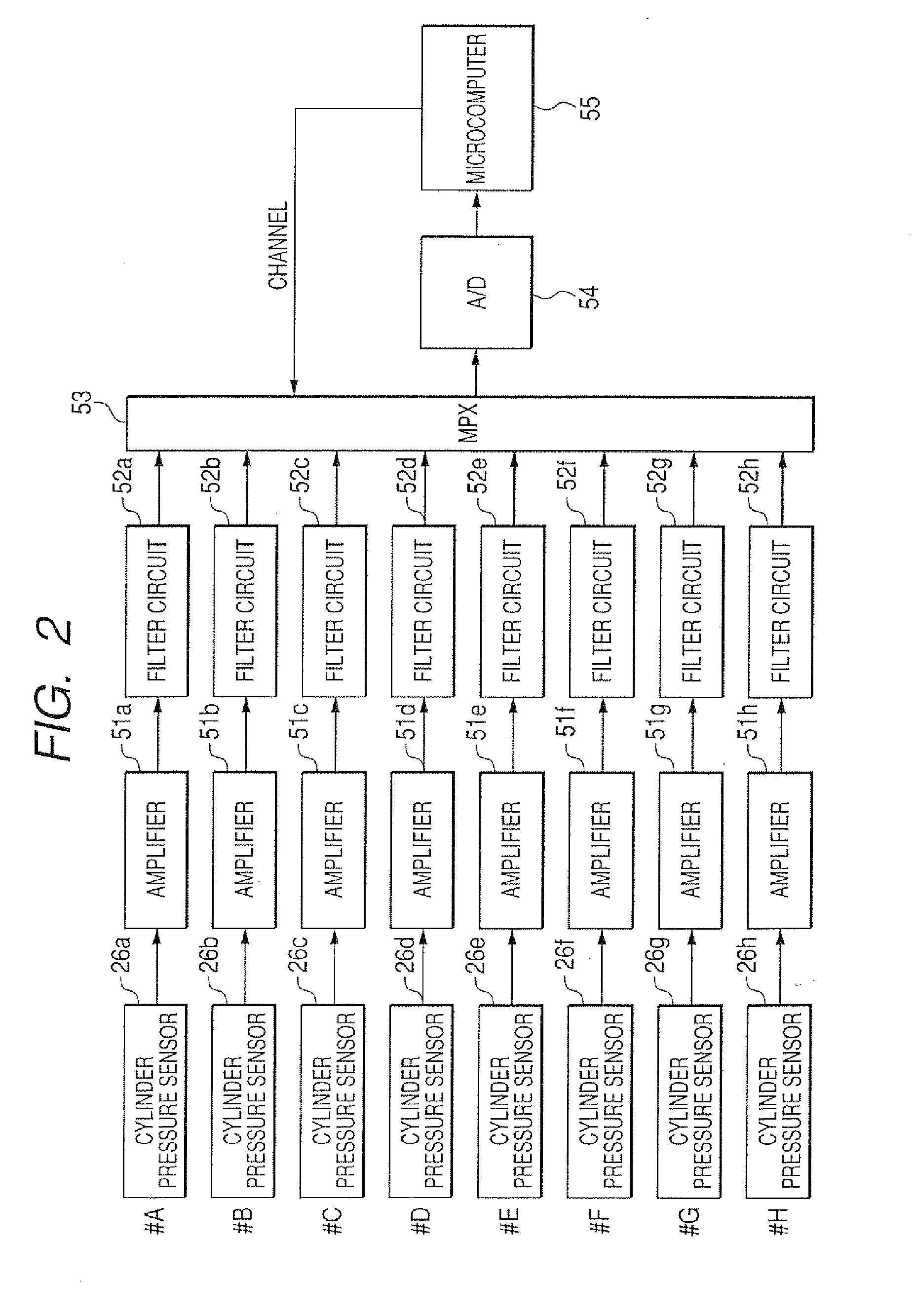
[0016]In general, such cylinder pressure sensors produce analog sensor signals, and such a control apparatus preferably comprises a single A / D (analog to digital) converter circuit, a signal selector circuit such as a multiplexer, and timing adjustment circuitry (e.g., implemented as a microcomputer) which controls the signal selector circuit. The timing adjustment circuitry selects successive ones of the analog sensor signals during respective selection intervals, which correspond to respective angular regions. That is to say, the start of each angular region occurs in synchronism with a signal sampling interval changeover timing, at which the cylinder pressure sensor signal for the next cylinder in the firing sequence is selected for A / D conversion. Successive sets of digital data are thereby acquired, corresponding to respective cylinders of the engine.
[0017]By using a single A / D converter in common for all of the engine cylinders in that way, the amount of hardware required to implement the control apparatus can be reduced, by comparison with providing separate A / D converters for each of the cylinders. However the invention can be equally applied to a system in which respective A / D converters are provided for each of the cylinder pressure sensors, in which case the outputted digital signals from the A / D converters would be multiplexed, i.e., successively selected in intervals corresponding to respective angular regions.
[0018]As applied to a fuel injection type of internal combustion engine, which can operating in a plurality of different fuel injection control modes (having respectively different timings of injection of fuel), the timing adjustment circuitry sets the timing of each of the data acquisition ranges in accordance with the fuel injection control mode that is currently being applied.
[0019]Hence, since the timing of each angular region can be adjusted in accordance with the timing at which fuel is injected into a combustion chamber, the combustion condition within the combustion chamber during each interval of combustion can be effectively monitored.
[0020]In particular, the invention is applicable to a multi-cylinder internal combustion engine having an exhaust gas cleansing device installed in the engine exhaust system, such as a DPF (diesel particulate filter) of a diesel engine, in which the fuel injection control circuitry establishes various fuel injection modes, such as a normal fuel injection mode during normal operation of the engine, and also establishes a regeneration control mode when regeneration of the DPF is to be performed. In the regeneration control mode the timings of fuel injections are delayed, by comparison with the normal fuel injection mode, such as to produce combustion conditions that will result in regeneration of the DFP as described hereinabove. With the present invention, the timing adjustment circuitry selectively alters the timing of the angular regions in accordance with whether or not the regeneration control mode is established. In that way, the combustion conditions in the cylinders during operation in the regeneration control mode can be suitably monitored.

Problems solved by technology

Hence even in the case of an engine having only a small number of cylinders, if multiplexing is applied to the cylinder pressure sensor signals so that data can only be acquired periodically from each cylinder pressure sensor during a small range of crank angle variation, it becomes difficult to adequately monitor the combustion conditions within the cylinders while engine control for regeneration of an exhaust gas purification device is in progress.

Method used


Image

  • Apparatus for controlling timings of intervals in which combustion chamber pressure data are acquired from output signals of cylinder pressure sensors of multi-cylinder internal combustion engine
  • Apparatus for controlling timings of intervals in which combustion chamber pressure data are acquired from output signals of cylinder pressure sensors of multi-cylinder internal combustion engine
  • Apparatus for controlling timings of intervals in which combustion chamber pressure data are acquired from output signals of cylinder pressure sensors of multi-cylinder internal combustion engine

Examples


Embodiment Construction

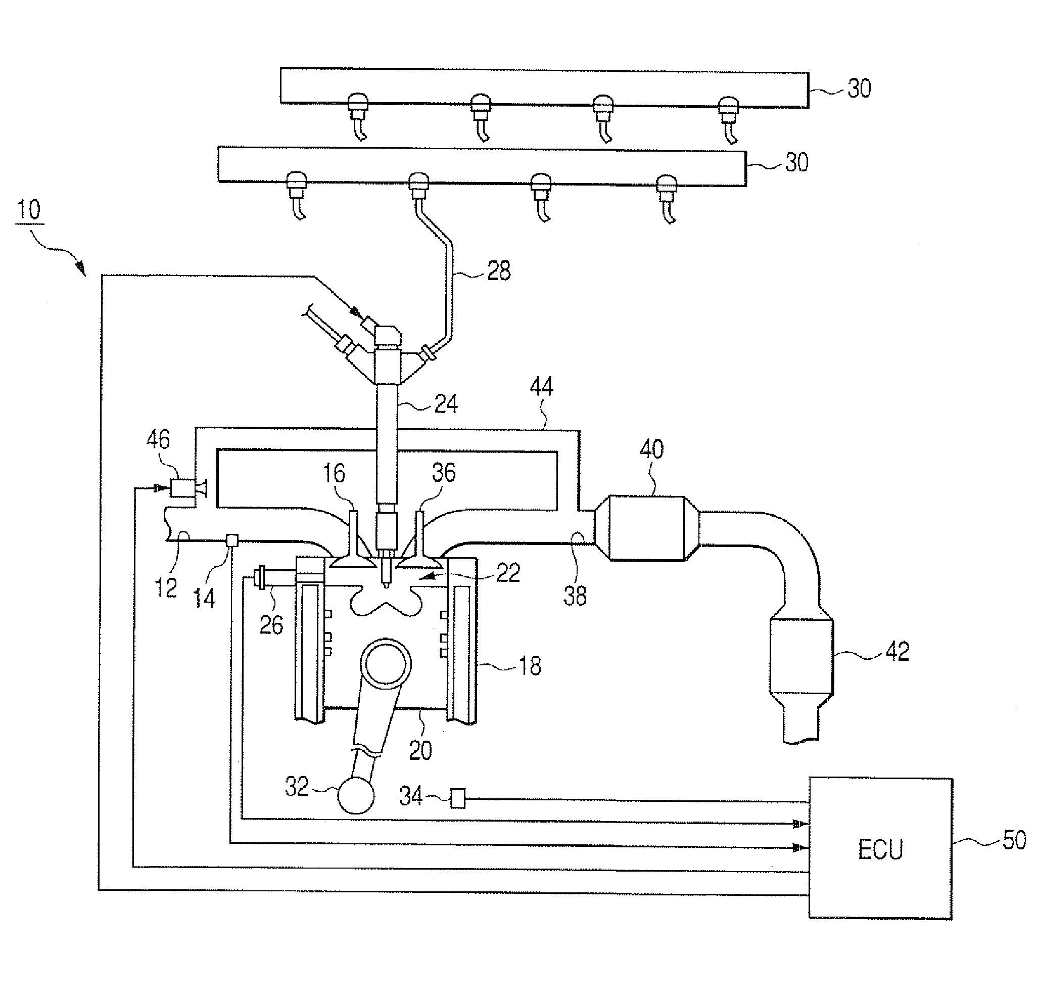
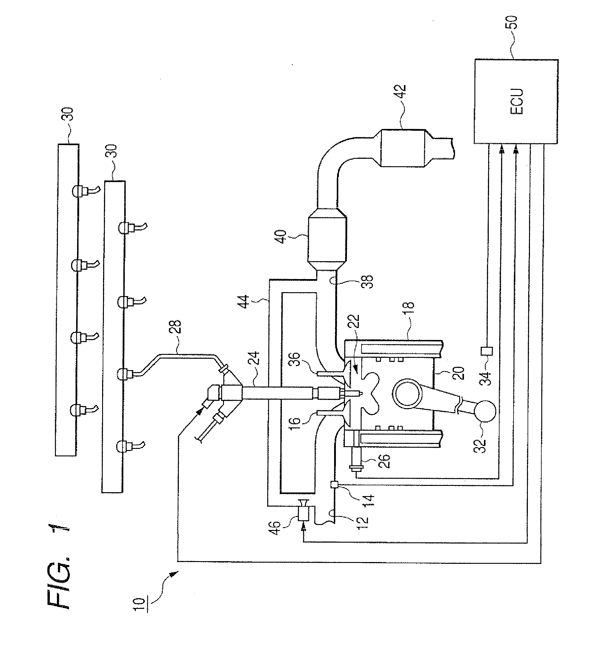
[0048]A first embodiment will be described in the following, which is incorporated in an engine system formed of a fuel injection control apparatus and a common-rail type of diesel engine of a vehicle. FIG. 1 shows the overall configuration of the engine system (with only one of the cylinders being illustrated), in which an 8-cylinder diesel engine 10 has an intake manifold 12 that is provided with an intake pressure sensor 14 for detecting the pressure within the intake manifold 12. Each of the cylinders has an identical configuration to that shown in FIG. 1. The intake manifold 12 communicates via a intake valve 16 with a combustion chamber 22 of the cylinder, with the combustion chamber 22 being formed between a cylinder block 18 and a piston 20 of the cylinder. A tip portion of a fuel injector 24 protrudes into the combustion chamber 22, for injecting controlled amounts of fuel into the combustion chamber 22. A cylinder pressure sensor 26 has a portion thereof exposed to the int...


PUM


Abstract

A control apparatus for a multi-cylinder internal combustion engine includes pressure sensors used for acquiring combustion chamber pressure data for each engine cylinder, during each of a series of selection intervals respectively corresponding to that cylinder, with each selection interval corresponding to a specific angular displacement of the crankshaft and having a timing determined with respect to a reference piston position in the corresponding cylinder. The timing of the selection intervals is adjusted in accordance with current conditions of the engine, such as a fuel injection mode, to be appropriate for monitoring combustion conditions in the cylinders.

Description

CROSS-REFERENCE TO RELATED APPLICATIONS[0001]This application is based on and incorporates herein by reference Japanese Patent Application No. 2006-325288 filed on Dec. 1, 2006.BACKGROUND OF THE INVENTION[0002]1. Field of Application[0003]The present invention relates to an apparatus for controlling the timings of intervals in which combustion chamber pressure data are acquired based on output signals from cylinder pressure sensors that detect pressure within respective combustion chambers of a multi-cylinder internal combustion engine, and for controlling operating parameters of the engine based on the acquired data.[0004]2. Description of Related Art[0005]A related type of control apparatus is described for example in Japanese patent No. 2893233, designated in the following as reference document 1, whereby the combustion conditions within respective cylinders of a 4-cylinder internal combustion engine are judged based on output signals from four cylinder pressure sensors, with eac...

Claims


Application Information

Patent Timeline
IPC IPC(8): F02D41/00
CPCF02D35/02F02D41/009F02D35/023F02D2041/281F02D2250/14
Inventor KOJIMA, KAZUOHARAGUCHI, HIROSHIMORIMOTO, YOUHEI
Owner DENSO CORP
Learn More