
Laminate for reflection film

Inactive Publication Date: 2008-06-05
ASAHI GLASS CO LTD
View PDF1 Cites 13 Cited by
  • Summary
  • Abstract
  • Description
  • Claims
  • Application Information

AI Technical Summary

Benefits of technology

[0017]The laminate of the present invention has an increased reflectance in the visible region since silver is used as the material of the metal film, and is excellent in durability also and is thereby useful as an optical member for a display, and contributes to improvement of brightness of the display and easy optical design. Further, the laminate of the present invention requires no formation of an extra layer to prevent oxidation and is thereby excellent in productivity. Further, it has a high reflectance and is excellent in durability such as moisture resistance and is thereby useful particularly as an optical member for a rear projection TV in which the number of reflection is large.

Problems solved by technology

However, although silver has a high reflectance in the visible region as compared with aluminum, its durability such as moisture resistance and salt water resistance tends to be poor, its film tends to be weak and is likely to be scarred due to poor adhesion to a substrate.
However, this laminate has such a problem that since oxygen is introduced when the Al2O3 film on the opposite side of the Ag film from the substrate is produced, silver is likely to be oxidize, thus lowering the reflectance.
However, since the reflection film is a single film of silver, only adhesion between the Ag film and the substrate is disclosed, and adhesion of the Ag film to another layer is not evaluated at all.
However, such reflection films have a problem in that the reflectance in the visible region is low.

Method used


Image

  • Laminate for reflection film
  • Laminate for reflection film

Examples


examples

[0057]Now, the present invention will be described in detail with reference to Examples, but the present invention is by no means restricted thereto.

examples 1 to 4

[0058]A soda lime glass substrate having a thickness of 1.1 mm was cleaned and set in a batch-system sputtering apparatus, and as targets, a gallium-doped zinc oxide target (gallium oxide content: 5.7 mass %, zinc oxide content: 94.3 mass %), an Au-doped silver alloy target (Au content: 1 at %, silver content: 99 at %), a silica target (SiO2 content: 99.9 at %) and an oxygen-deficient niobium oxide target (Nb2O5-x (X=0 to 1)) were respectively set at positions opposing to the substrate, and the interior of the vacuum chamber was evacuated to 8×10⁻⁴ Pa. Then, the following films A) to E) were sequentially formed to obtain a laminate.

A) Formation of Underlayer (Zinc Oxide Film)

[0059]By an RF sputtering method, a gallium-doped zinc oxide film was formed in a thickness of 6 nm on the glass substrate in an Ar gas atmosphere at an applied power density of 1.6 W / cm2 under a sputtering pressure of 0.3 Pa by means of a gallium-doped zinc oxide target. The substrate was not heated. The compos...

example 5

Comparative Example

[0072]A laminate was formed in the same manner as in Example 1 except that as the initial layer of the low refractive index film, a silicon oxide film was formed in a thickness of 3 nm by an RF sputtering method in an Ar gas atmosphere (i.e. an atmosphere containing no nitrogen) at an applied power density of 2.4 W / cm2 under a sputtering pressure of 0.3 Pa by means of a silica target. The laminate was evaluated in the same manner as in Example 1, and the results are shown in Table 2.


PUM

PropertyMeasurementUnit
Percent by massaaaaaaaaaa
Thicknessaaaaaaaaaa

Abstract

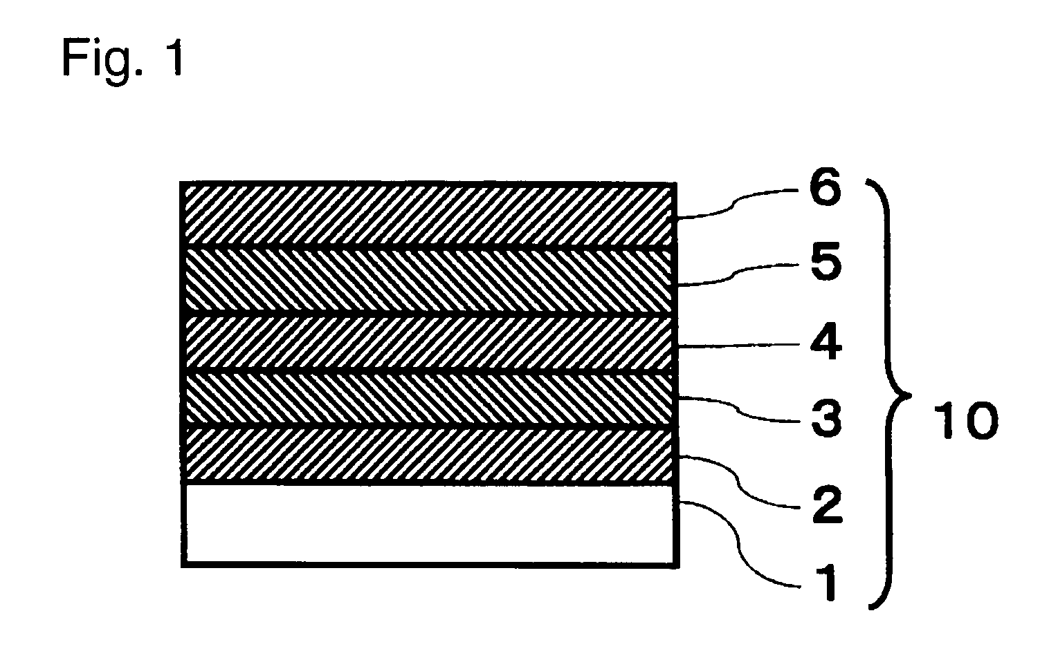
To provide a laminate having a high reflectance in the entire visible region and having excellent durability such as moisture resistance and salt water resistance.A laminate comprising a substrate, and a silver film, an adhesion-improving film, a low refractive index film and a high refractive index film formed in this order on the substrate, wherein at least a layer on the adhesion-improving film side in the low refractive index film is formed by a radio frequency sputtering method by means of an oxide target using a sputtering gas containing nitrogen, the adhesion improving film has an extinction coefficient of at most 0.1 and has a thickness of from 0.5 to 4 nm, the low refractive index film has an extinction coefficient of at most 0.01, and the high refractive index film has an extinction coefficient of at most 0.01.

Description

TECHNICAL FIELD[0001]The present invention relates to a laminate used mainly for a reflection member for a projection TV.BACKGROUND ART[0002]Heretofore, as a reflection mirror to be used for electronic equipment such as a display, a mirror utilizing a metal film for reflection has been widely used. For improvement of brightness of the electronic equipment and for energy saving, it is important to increase the reflectance of the reflection mirror. For example, in a liquid crystal display used for e.g. a cell-phone, a mirror which reflects backlight is used, and for the mirror, a film is used as a substrate for weight saving, and a reflection mirror having a high reflectance is required. Further, to project an image on a large screen of e.g. a projection TV, a plurality of reflection mirrors are required in an optical system, and accordingly the quantity of light tends to decrease as the number of reflection increases. Consequently, the finally obtained quantity of light tends to be s...

Claims


Application Information

Patent Timeline
IPC IPC(8): B32B15/04B32B19/00
CPCG02B1/105Y10T428/265G02B5/0858Y10T428/31678G02B1/14G02B5/08
Inventor HIRUMA, TAKEHIKOSHIN, NAOKO
Owner ASAHI GLASS CO LTD
Learn More