
Head substrate, printhead, head cartridge, and printing apparatus

a printing apparatus and head substrate technology, applied in printing, inking apparatus, etc., can solve the problems of adversely affecting the ink discharge characteristic, so-called power loss, adversely affecting the durable service life of heaters, etc., and achieve the effect of reducing the distance between the pad and the element array, reducing the wiring resistance of the power supply, and reducing the area

Inactive Publication Date: 2008-06-05
ABLYNX NV +1
View PDF14 Cites 18 Cited by
  • Summary
  • Abstract
  • Description
  • Claims
  • Application Information

AI Technical Summary

Benefits of technology

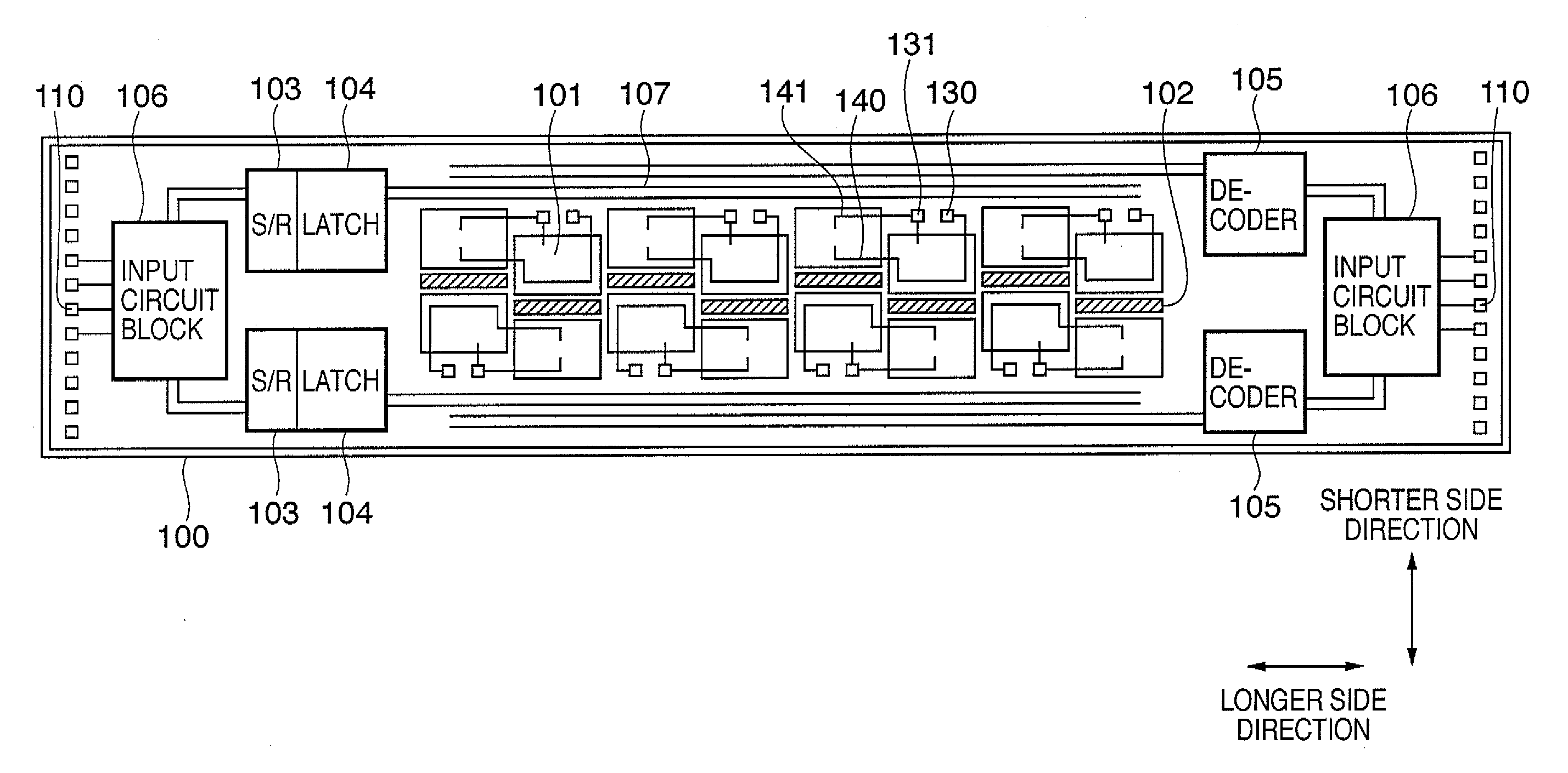
[0022]For example, a head substrate according to this invention is capable of increasing the layout efficiency, reducing power loss, and reducing the substrate area by effectively utilizing the area of a head substrate on which ink supply channels are staggered.
[0027]The invention is particularly advantageous since a power supply pad is arranged in an area formed when ink supply channels and corresponding element arrays are staggered, and the power supply pad supplies power to an element array adjacent to the power supply pad. The area can be effectively utilized, and the distance between the pad and the element array can be shortened. Hence, the wiring resistance for power supply can be suppressed to reduce power loss.
[0029]Since the power supply line need not be made thick, the layout area can be reduced, contributing to downsizing the head substrate.

Problems solved by technology

The increase in wiring resistance causes so-called power loss because power, which should be originally consumed by heaters, is consumed by the wiring to a certain degree.
If the original power supply voltage is increased to compensate for the power loss, this adversely affects the durable service life of heaters.
Further, heat generated by power consumption by the wiring raises the temperature of the printhead itself, adversely affecting the ink discharge characteristic.

Method used


Image

  • Head substrate, printhead, head cartridge, and printing apparatus
  • Head substrate, printhead, head cartridge, and printing apparatus
  • Head substrate, printhead, head cartridge, and printing apparatus

Examples


Embodiment Construction

[0050]Preferred embodiments of the present invention will now be described in detail in accordance with the accompanying drawings. The same reference numerals denote the same parts, and a description thereof will not be repeated.

[0051]In this specification, the terms “print” and “printing” not only include the formation of significant information such as characters and graphics, but also broadly includes the formation of images, figures, patterns, and the like on a print medium, or the processing of the medium, regardless of whether they are significant or insignificant and whether they are so visualized as to be visually perceivable by humans.

[0052]Also, the term “print medium” not only includes a paper sheet used in common printing apparatuses, but also broadly includes materials, such as cloth, a plastic film, a metal plate, glass, ceramics, wood, and leather, capable of accepting ink.

[0053]Furthermore, the term “ink” (to be also referred to as a “liquid” hereinafter) should be e...


PUM


Abstract

The objective of this invention is to provide a head substrate capable of increasing the layout efficiency by arranging circuit elements in a free area of the head substrate on which ink supply channels are staggered. More specifically, the circuit elements connected to a plurality of element arrays are arranged on the free area.

Description

BACKGROUND OF THE INVENTION[0001]1. Field of the Invention[0002]The present invention relates to a head substrate, printhead, head cartridge, and printing apparatus. Particularly, the present invention relates to a head substrate prepared by forming, on the same substrate, an electrothermal transducer for generating heat energy necessary to print, and a driver circuit for driving the electrothermal transducer, a printhead using the head substrate, a head cartridge using the printhead, and a printing apparatus.[0003]2. Description of the Related Art[0004]The electrothermal transducers (heaters) and driver circuits of a printhead mounted in a conventional inkjet printing apparatus are formed on the same substrate by a semiconductor process technique as disclosed in, for example, U.S. Pat. No. 6,290,334. There has already been proposed a substrate on which an ink supply channel for supplying ink is arranged on the substrate and heaters are arrayed at positions opposite to each other ne...

Claims


Application Information

Patent Timeline
Patent Type & Authority Applications(United States)
IPC IPC(8): B41J2/14
CPCB41J2/04515B41J2/04541B41J2/04543B41J2202/20B41J2/0458B41J2/14072B41J2/0455
Inventor FURUKAWA, TATSUO
Owner ABLYNX NV
Learn More