Chip Seal Ring for Enhancing the Operation of an On-Chip Loop Antenna

a technology of loop antenna and seal ring, which is applied in the field of on-chip antennas, can solve the problems of reducing the effectiveness affecting the operation of the loop antenna,

Active Publication Date: 2008-06-05
GLOBALFOUNDRIES US INC
View PDF4 Cites 28 Cited by
  • Summary
  • Abstract
  • Description
  • Claims
  • Application Information

AI Technical Summary

Benefits of technology

[0004]In one embodiment, the present disclosure is directed to an integrated circuit chip. The integrated circuit chip comprises a substrate having a lateral outer periphery and a loop antenna applied to the substrate within the lateral outer periphery. Semiconductor circuitry is located within the lateral outer periphery. A me

Problems solved by technology

The main purpose of the seal ring is to prevent ionic or other contamination from entering the integrated circuit aboard the chip, since ionic or other contamination can cause a degradation of the operating characteristics of components, such as transistors, within the integrated circuit chip.
The presence of the seal ring can significantly reduce the effectiveness of the

Method used


Image

  • Chip Seal Ring for Enhancing the Operation of an On-Chip Loop Antenna
  • Chip Seal Ring for Enhancing the Operation of an On-Chip Loop Antenna
  • Chip Seal Ring for Enhancing the Operation of an On-Chip Loop Antenna

Examples


first embodiment

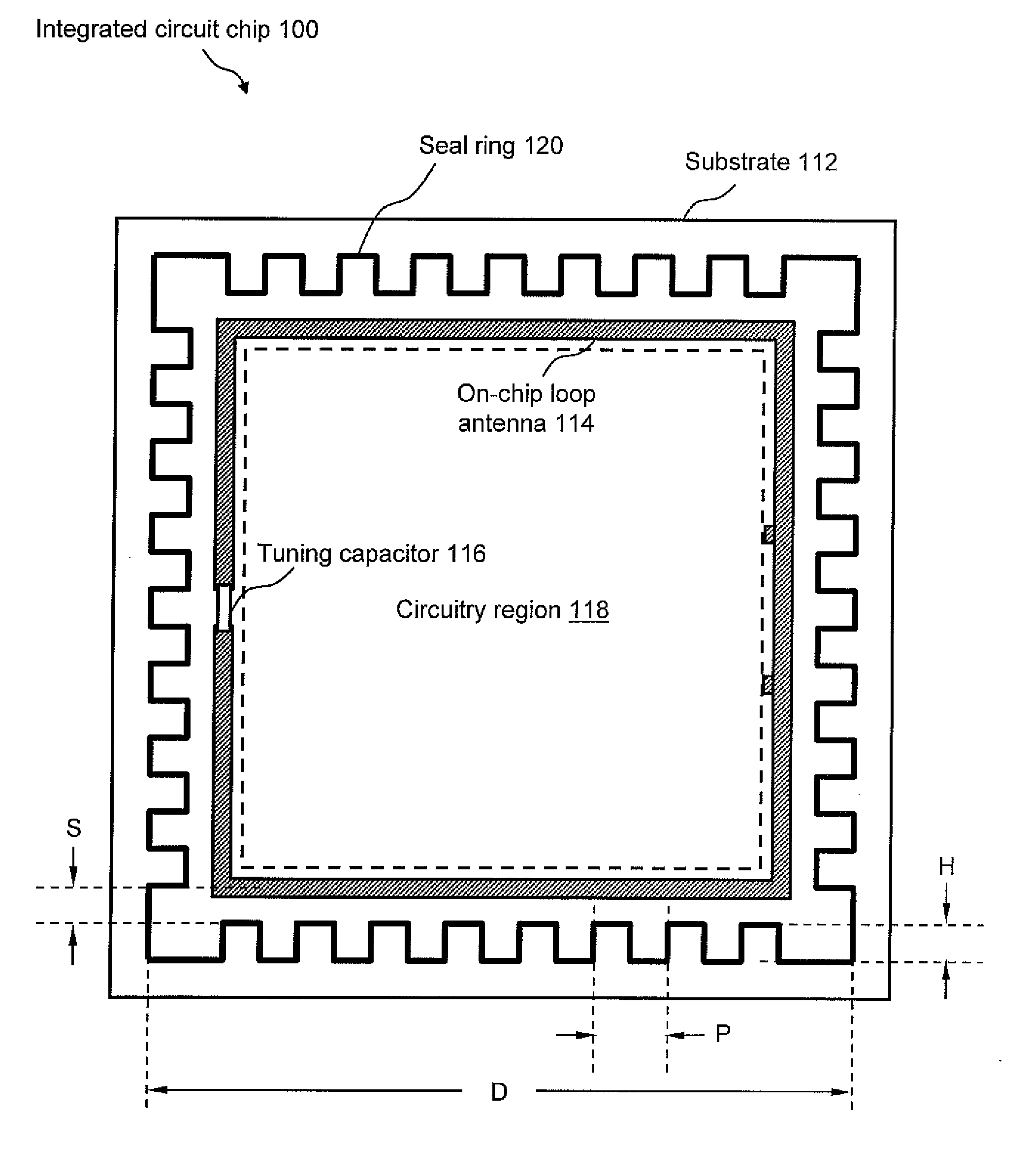
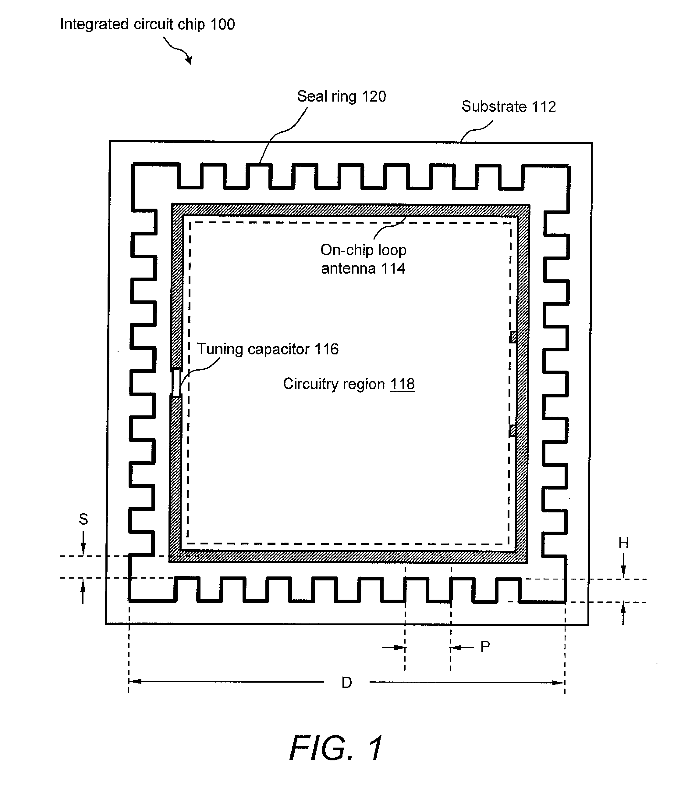
[0011]FIG. 1 illustrates a top view of an integrated circuit chip 100 that includes a chip seal ring made in accordance with the present invention. As those skilled in the art will understand, integrated circuit chip 100 may be any chip that utilizes an on-chip loop antenna, such as a radio-frequency identification (RFID) chip, among others. Integrated circuit chip 100 includes a substrate 112 that may be a standard silicon substrate used for semiconductor fabrication. Substrates chosen for integrated circuit chips that include on-chip loop antennas are often formed of more highly resistive doped silicon or other material. An on-chip loop antenna 114 may be formed on substrate 112, along with an associated tuning capacitor 116, which may be located across a break in the antenna. On-chip loop antenna 114 may be, for example, a resonant “small loop” antenna designed for a certain operating frequency. The size of tuning capacitor 116 would typically be chosen to resonate on-chip loop a...

second embodiment

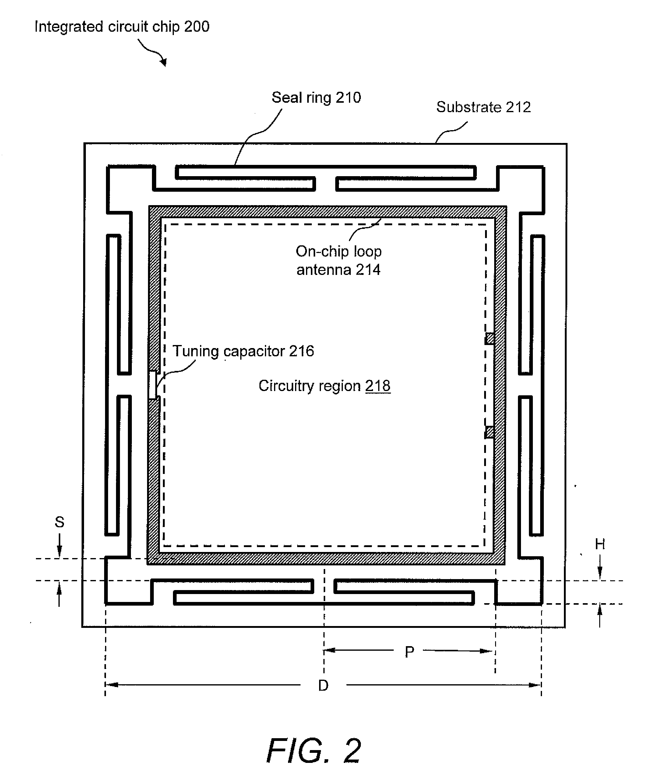
[0019]FIG. 2 illustrates a top view of an integrated circuit chip 200 that includes a chip seal ring 210 made in accordance with the present invention. Integrated circuit chip 200 includes a substrate 212, an on-chip loop antenna 214, a tuning capacitor 216, and a circuitry region 218, which may be substantially identical in form, arrangement, and function to substrate 112, on-chip loop antenna 114, tuning capacitor 116, and circuitry region 118, respectively, of integrated circuit chip 100 of FIG. 1.

[0020]In the example shown, seal ring 210 is located between the outer edges of substrate 212 and on-chip loop antenna 214 and has at least a portion of its length folding back on itself in order to form a linear loaded serpentine-shaped chip seal ring. As mentioned above, this linear loaded serpentine shape provides seal ring 210 with an RF choke that increases the inductance and resistance and, thereby, increases the impedance of the seal ring in order to reduce the magnitude of the c...


PUM


Abstract

A chip seal ring that maintains the chip seal ring as a continuous barrier to contamination, while at the same time creating a desirable electrical feature in the seal ring that enables the use of an on-chip loop antenna. In one embodiment, at least a portion of the chip seal ring has a serpentine configuration, such as a square wave, triangle wave, or curved geometry, that increases the reactance and resistance of the seal ring so as to mitigate the adverse induced currents created by the magnetic coupling effects between the on-chip antenna and the seal rings, thereby improving the efficiency of an on-chip loop antenna in the presence of the seal ring.

Description

FIELD OF THE DISCLOSURE[0001]The present disclosure generally relates to the field of on-chip antennas. In particular, the present disclosure is directed to a modified chip seal ring for the purpose of mitigating the negative effects of a seal ring and thereby enhancing the operation of an on-chip loop antenna.BACKGROUND[0002]When it is desirable for a radio frequency (RF) chip, such as a radio frequency identification (RFID) chip, to use an on-chip antenna, one of the most efficient designs to use is a resonant small loop antenna. A small loop antenna is one with a total radiator length (or circumference for a single turn loop antenna) that is less than one quarter of a wavelength. Very often these on-chip loop antenna radiating elements are formed with the largest area single turn loop of a low resistance wire that is broken at one point and, thus, the single turn loop is seen as a one turn inductor. Such loop antennas typically have a tuning capacitor connected across the break a...

Claims


Application Information

Patent Timeline
IPC IPC(8): H01Q11/12H01Q1/42
CPCH01Q7/00H01Q1/2283H01L23/585H01L23/66H01L2223/6677H01L2924/0002H01L2924/00
Inventor BARRY, ROBERT L.
Owner GLOBALFOUNDRIES US INC
Why Eureka
Try Eureka