
Orthtic device and method for providing static and dynamic stability to the medial arch and subtalar bone complex

Inactive Publication Date: 2008-06-05
SPICER ROBERT D
View PDF12 Cites 10 Cited by
  • Summary
  • Abstract
  • Description
  • Claims
  • Application Information

AI Technical Summary

Benefits of technology

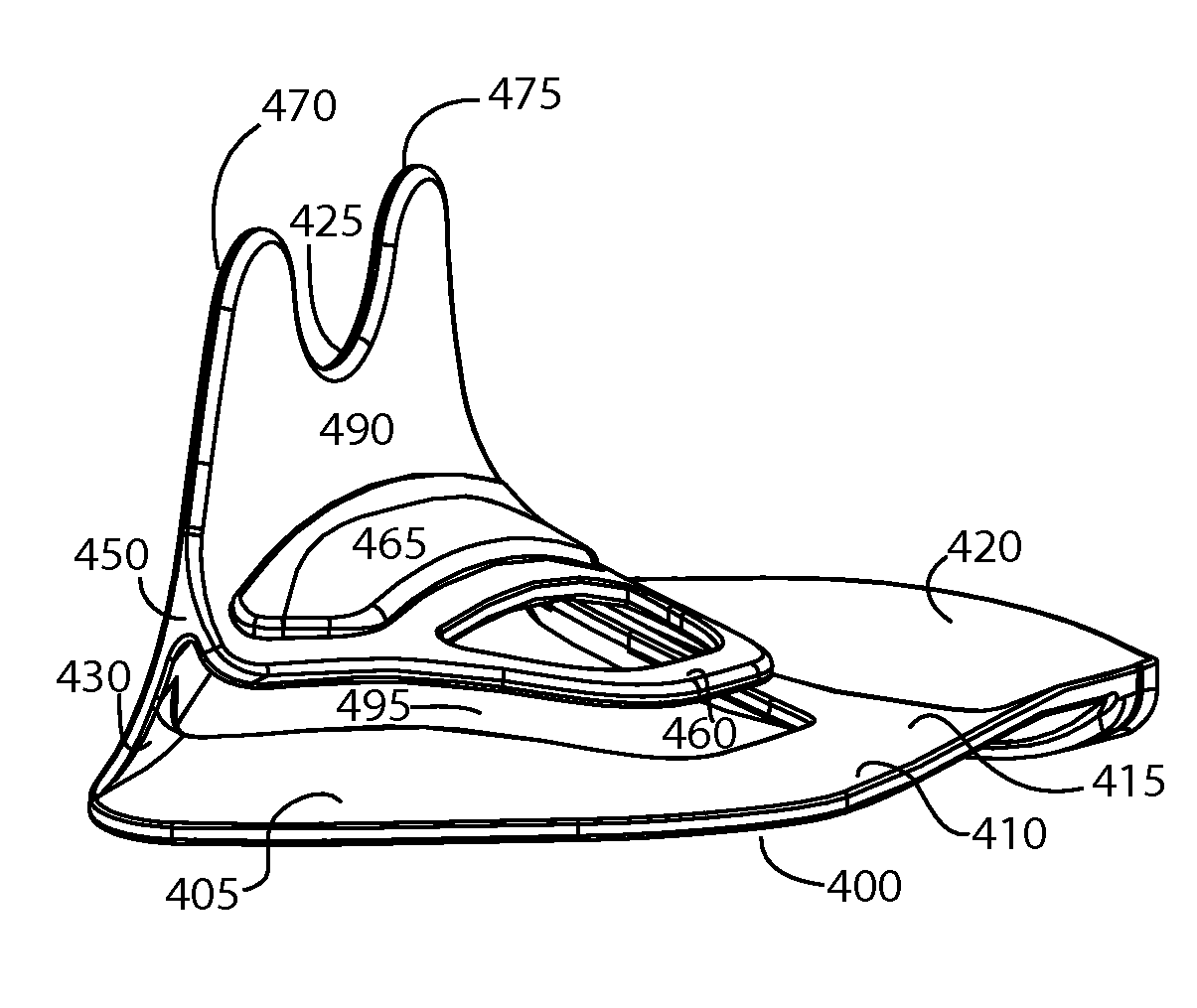
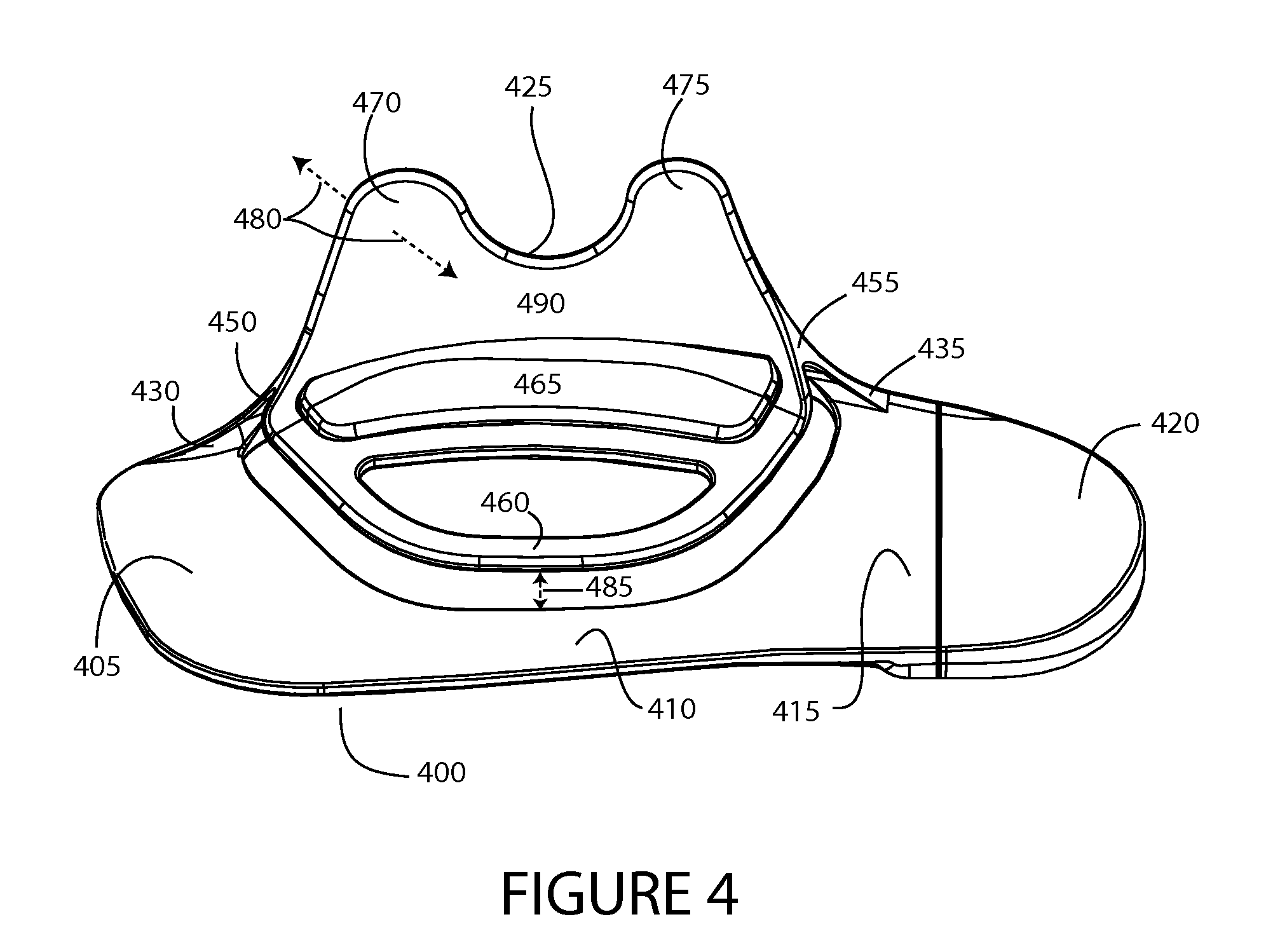
[0017]In another aspect of an exemplary embodiment of the invention, an integrally molded orthotic device for a foot is configured to provide static and dynamic stability. The device includes a base, a dynamic vertical support flange coupled to the base and configured to controllably pivot and apply pressure against corresponding medial areas of the foot, and a cantilever arch support pivotally coupled to the base and configured to pivot downwardly upon application of a downward force, the dynamic vertical support flange may be operably coupled to the cantilever arch support and configured to pivot and apply pressure against corresponding medial areas of the foot when the cantilever arch support pivots downwardly. Means for attaching an arch support pad configured to cushion an arch of the foot may be provided. Additionally, means for attaching a heel cup configured to cushion a heel of the foot may also be provided.
[0018]In another aspect of an exemplary embodiment of the invention, a method of stabilizing a medial arch and subtalar bone complex is provided. The method includes steps of translating a downward force exerted by a foot during walking motion into pivotal motion of a medial support flange, urging the medial support flange against corresponding areas of the foot to provide a stabilizing force, relieving the downward force; and relieving the stabilizing force as the downward force is relieved.

Problems solved by technology

These orthotic devices are ineffective for most people because the appearance of the fallen arch is only one aspect of the dysfunction.
In addition, excessive pronation, and a myriad of accompanying mechanical insufficiencies occur in the dynamic mode of the foot.
Currently available orthotic inserts do not address the dynamic mode excessive pronation, nor do they address the other associated mechanical insufficiencies of the foot during this mode.
The long plantar ligament is a shorter ligament and therefore represents a less effective passive stabilizer because of the lower constraining force it applies to the longitudinal arch.
Lastly, the plantar calcaneonavicular is the shortest and least effective passive stabilizer.
Ligaments that have been over stretched lose their elastic properties (ligamentous laxity) and become incompetent.
This incompetence can cause misalignment of the bones that are supported by the ligaments.
As with ligaments, overstretching of tendons may cause inelasticity and incompetence of the tendon.
As a result of this excessive and prolonged pronation, the posterior tibial tendon is unable to lock the bones of the mid-foot to create a rigid lever for toe off creating excessive forces on the PTT.
Over time there is a gradual attenuation of the medial static constraints of the longitudinal arch mechanism and the foot losses its mechanical advantage during gate.
Repeated excessive forces on the PTT cause eventual incompetence of the PTT and result in hyperpronation.
Unfortunately, however, conventional orthopedic corrective devices suffer shortcomings, as none provide an orthotic specifically adapted to provide improved stability of the foot structure during the static and dynamic modes of the foot.
Specifically, no known prior art orthotics provide a dynamically adjusting structure that exerts lateral corrective pressure.

Method used


Image

  • Orthtic device and method for providing static and dynamic stability to the medial arch and subtalar bone complex
  • Orthtic device and method for providing static and dynamic stability to the medial arch and subtalar bone complex
  • Orthtic device and method for providing static and dynamic stability to the medial arch and subtalar bone complex

Examples


Embodiment Construction

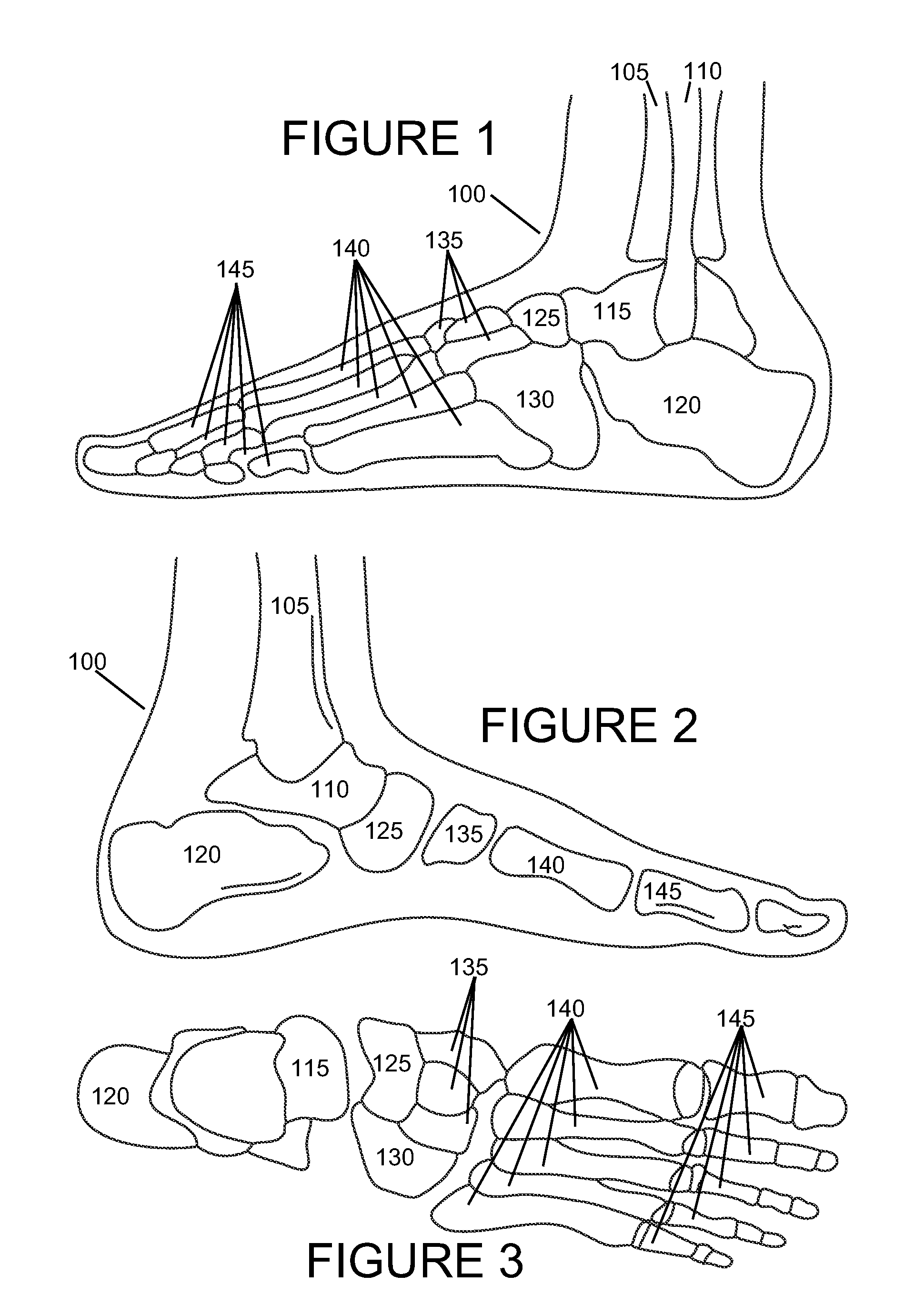
[0034]With reference to FIGS. 1-3, there is shown a typical human foot 100, and (in FIGS. 1 and 2) the tibia 105 and fibula 110, the two lower bones of the leg. Below the tibia 105 and fibula 110, there is the talus 110 (i.e., the “ankle bone”). Positioned below and rearwardly of the talus 110 is the calcaneus 115 (i.e., the heel bone). Positioned moderately below and forward of the talus 110 are the navicular 120 and the cuboid 125. Extending forwardly from the navicular 120 are three cuneiform bones 140. Extending forwardly from the cuneiform bones 140 and from the cuboid 125 are the five metatarsals 130. Forwardly of the metatarsals 130 are the phalanges 135.

[0035]An exemplary orthotic device according to principles of the invention provides static and dynamic stability to the medial arch by decreasing the effective vertical force applied to the plantar fascia, allowing it to function optimally, while providing dynamic horizontal stability to the subtalar bone complex during gate...


PUM


Abstract

Orthotic devices are configured to provide static and dynamic stability to the medial arch and subtalar bone complex. The orthotic device includes a resilient arch support configured to collapse under the weight of a user. Collapsing causes an operably coupled vertical support flange to pivotally urge the vertical support flange against corresponding medial areas of the foot. A method entails translating a downward force exerted by a foot during walking motion into pivotal motion of the vertical support flange. Pivotal motion urges the flange against corresponding areas of the foot to providing a stabilizing force. As the downward force is relieved, the stabilizing force is relieved and the medial support flange returns to its original position.

Description

RELATED APPLICATION[0001]This application claims the benefit of priority of U.S. provisional application 60 / 868,079, filed Nov. 30, 2006, the entire contents of which are incorporated herein by this reference.FIELD OF THE INVENTION[0002]This invention generally relates to orthopedic devices adapted to relieve or correct foot problems, and, more particularly, to an orthotic configured to provide static and dynamic stability to the medial arch and subtalar bone complex.BACKGROUND[0003]The mechanical features of the human foot are produced by the organization and function of its bones, joints, muscles, ligaments and tendons. The interaction of these anatomical components determines the efficacy of the foot in both the static and dynamic modes. When in the static mode, the foot acts as a load bearing structure designed to comfortably tolerate the forces associated with standing or sitting. In the static mode, while sitting, lying, or standing, the foot is at rest and the overall structu...

Claims


Application Information

Patent Timeline
IPC IPC(8): A43B7/14
CPCA43B7/1495A43B7/24A43B7/223
Inventor SPICER, ROBERT D.
Owner SPICER ROBERT D
Learn More