
Model simplification method for use in model-based development

Inactive Publication Date: 2008-05-29
TOYOTA JIDOSHA KK
View PDF2 Cites 11 Cited by
  • Summary
  • Abstract
  • Description
  • Claims
  • Application Information

AI Technical Summary

Benefits of technology

[0008]The present invention provides a model simplification method for use in model-based development to simplify a model base that is implemented in a vehicle ECU without significantly decreasing the calculation accuracy.
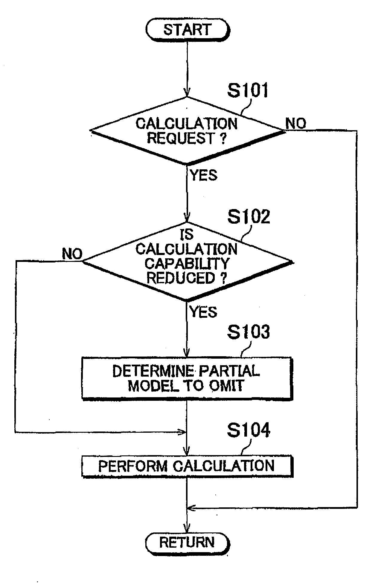
[0014]A sixth aspect of the present invention provides a calculation method using a model base, including: when a current processing capacity of the ECU is reduced during calculation of the specific value using the model base determined by the model simplification method for use in model-based development according to the above first to fourth aspects and implemented in the ECU, reducing the processing load of the specific value to or below the current processing capacity of the ECU by omitting partial models from the model base in order of ascending priority.
[0015]A seventh aspect of the present invention provides a calculation method using a model base, including: when a current processing capacity of the ECU is reduced during calculation of the first specific value or the second specific value using the model base determined by the model simplification method for use in model-based development according to the above fifth aspect and implemented in the ECU, reducing the processing load of the first specific value or the second specific value to or below the current processing capacity of the ECU by omitting partial models from the model base in order of increasing first ratio during the calculation of the first specific value, and by omitting partial models from the model base in order of increasing second ratio when calculating the second specific value.

Problems solved by technology

In practice, however, it is difficult to implement such a model base because of the enormous processing load on the ECU.
While omission of an arbitrarily selected partial model may reduce the processing load, it is likely to introduce significant errors in the calculation.

Method used


Image

  • Model simplification method for use in model-based development
  • Model simplification method for use in model-based development
  • Model simplification method for use in model-based development

Examples


Embodiment Construction

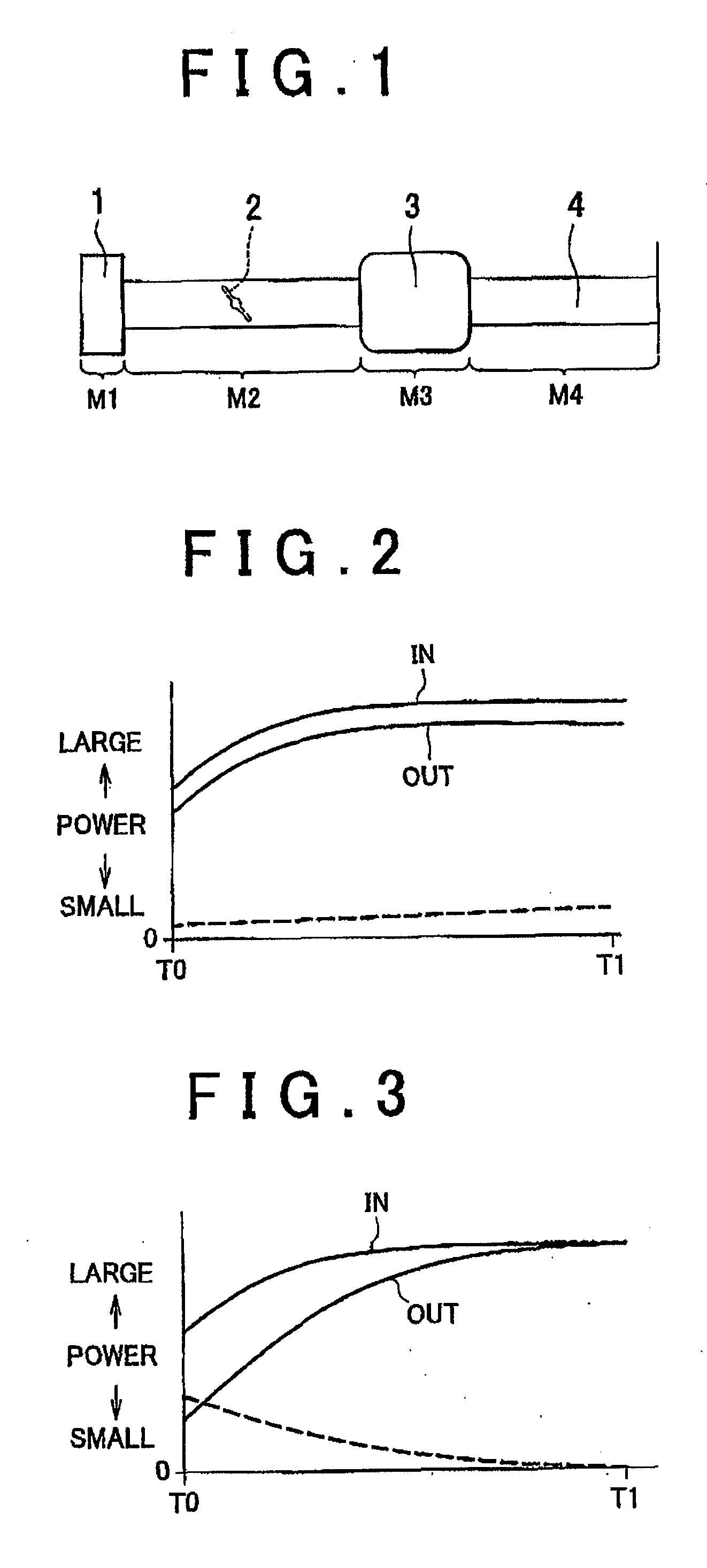
[0036]FIG. 1 is a schematic diagram showing an engine intake system. FIG. 1 shows an air filter 1, a throttle valve 2, a surge tank 3, and an intake port 4. In order to calculate the flow rate of intake air flowing into a cylinder in such an engine intake system, for example, using a model simplification method for use in model-based development in accordance this embodiment, first, a complete model base is prepared by modeling respective parts of the entire engine intake system, before determining a model base for implementation in a vehicle ECU. Using such a complete model base, it is possible to accurately calculate the flow rate of the intake air flowing into the cylinder, even when the engine is in a transient state. However, it is difficult for the vehicle ECU to calculate the intake air flow rate using the complete model base because of the enormous processing load. For implementation in the vehicle ECU, it is necessary to simplify the complete model base by ignoring (or disc...


PUM


Abstract

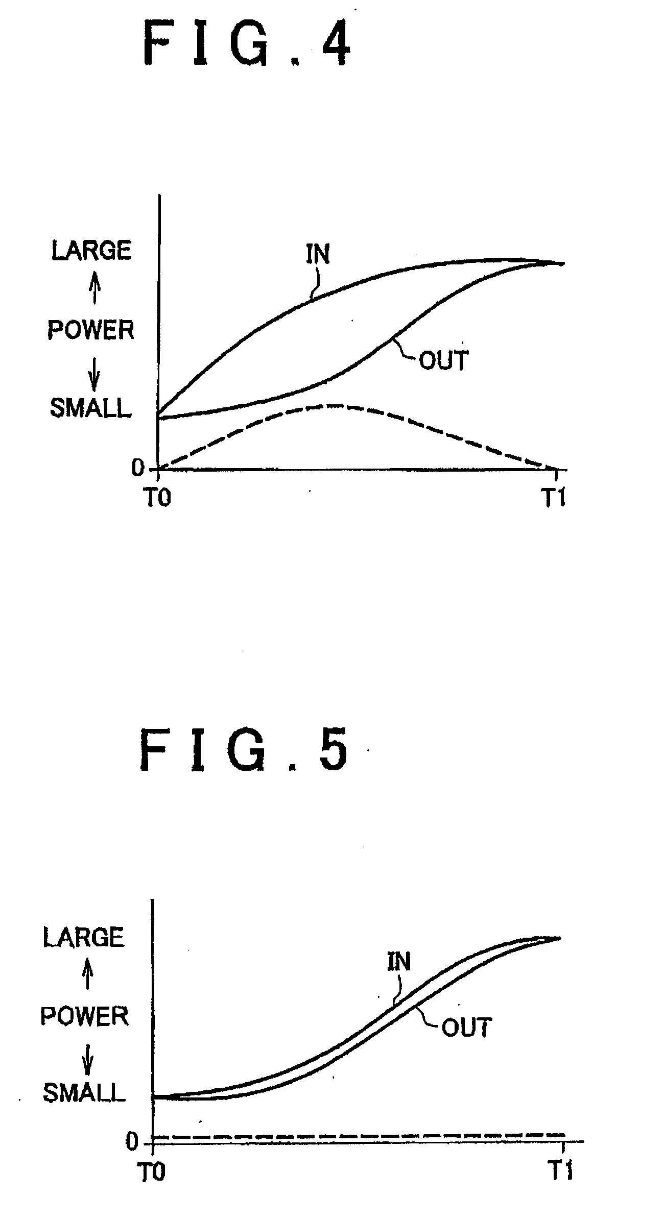
Determination values are obtained by calculating values for each partial model of a complete model base at each unit time, and by integrating absolute values of change amounts of the values and absolute value of change amount of a product of at least two values, according to the engine acceleration pattern. A set of the determination values including a specific determination value of a specific partial model having the most influence on a specific value calculated using the model base is selected, wherein the specific determination value is the largest among the determination values of all the partial models. A higher priority is assigned to a partial model with a higher determination value. The model base is determined by omitting a partial model from the complete model base in order of ascending priority until a desired processing load of calculating the specific value is obtained.

Description

INCORPORATION BY REFERENCE[0001]The disclosure of Japanese Patent Application No. 2006-320215 filed on Nov. 28, 2006 including the specification, drawings and abstract is incorporated herein by reference in its entirety.BACKGROUND OF THE INVENTION[0002]1. Field of the Invention[0003]The present invention relates to a model simplification method for use in model-based development.[0004]2. Description of the Related Art[0005]In recent years, proposals have been made to model an engine intake system for implementation in a vehicle ECU and to calculate using a model base, for example, an intake air amount during a transient period, which cannot be detected accurately with an airflow meter. In order to accurately calculate the intake air amount, it is ideal to implement a model base obtained by modeling the entire engine intake system in the ECU. In practice, however, it is difficult to implement such a model base because of the enormous processing load on the ECU.[0006]Therefore, it is ...

Claims


Application Information

Patent Timeline
IPC IPC(8): G06G7/70
CPCB60W10/04B60W2050/0039B60W2050/0041F02D41/1497F02D41/18F02D41/26G06F2217/80F02D2200/0402F02D2200/1004F02D2250/12F02D2250/21G06F17/5095F02D2041/1433B60W2050/0031G06F30/15G06F2119/08
Inventor DEGAKI, TAKANORI
Owner TOYOTA JIDOSHA KK
Learn More