Eureka AIR delivers breakthrough ideas for toughest innovation challenges, trusted by R&D personnel around the world.

Systems and methods for power and flow rate control

a technology of flow rate control applied in the field of fluid control, can solve the problems of negative pressure, increased vacuum, and current system and method of controlling the volumetric flow rate of the vacuum-based pump

Active Publication Date: 2008-05-29
JOHNSON & JOHNSON SURGICAL VISION INC
View PDF30 Cites 243 Cited by
  • Summary
  • Abstract
  • Description
  • Claims
  • Application Information

AI Technical Summary

Benefits of technology

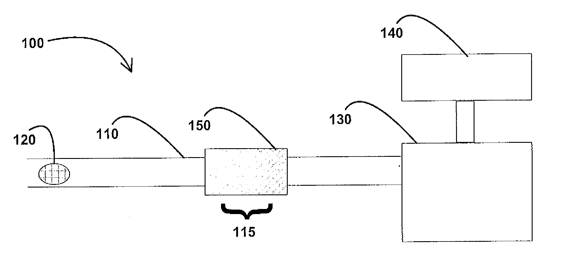
[0010]In accordance with one embodiment, an aspiration system includes an aspiration line having distal and proximal ends and an aspiration port defined in the distal end; a fluid transport device operatively coupled to the proximal end of the aspiration line; and a flow restrictor operatively coupled to the aspiration line in between the fluid transport device and the aspiration port. To measure occlusion within the line, first and second pressure sensors are utilized, the first sensor being operatively coupled to the aspiration line between the port and the restrictor and the second sensor being operatively coupled to the aspiration line between the restrictor and the fluid transport device. The pressure differential between the two sensors can provide an indication of the onset, presence, and / or elimination of an occlusion.

Problems solved by technology

The rate of fluid flow generated by a vacuum-based pump is generally higher than the rate of fluid flow generated by a volumetric flow based pump; however, current systems and methods for controlling the rate of volumetric flow for the vacuum-based pump, which typically involve adjusting the operative vacuum level, are imprecise, which raises safety and efficacy concerns.
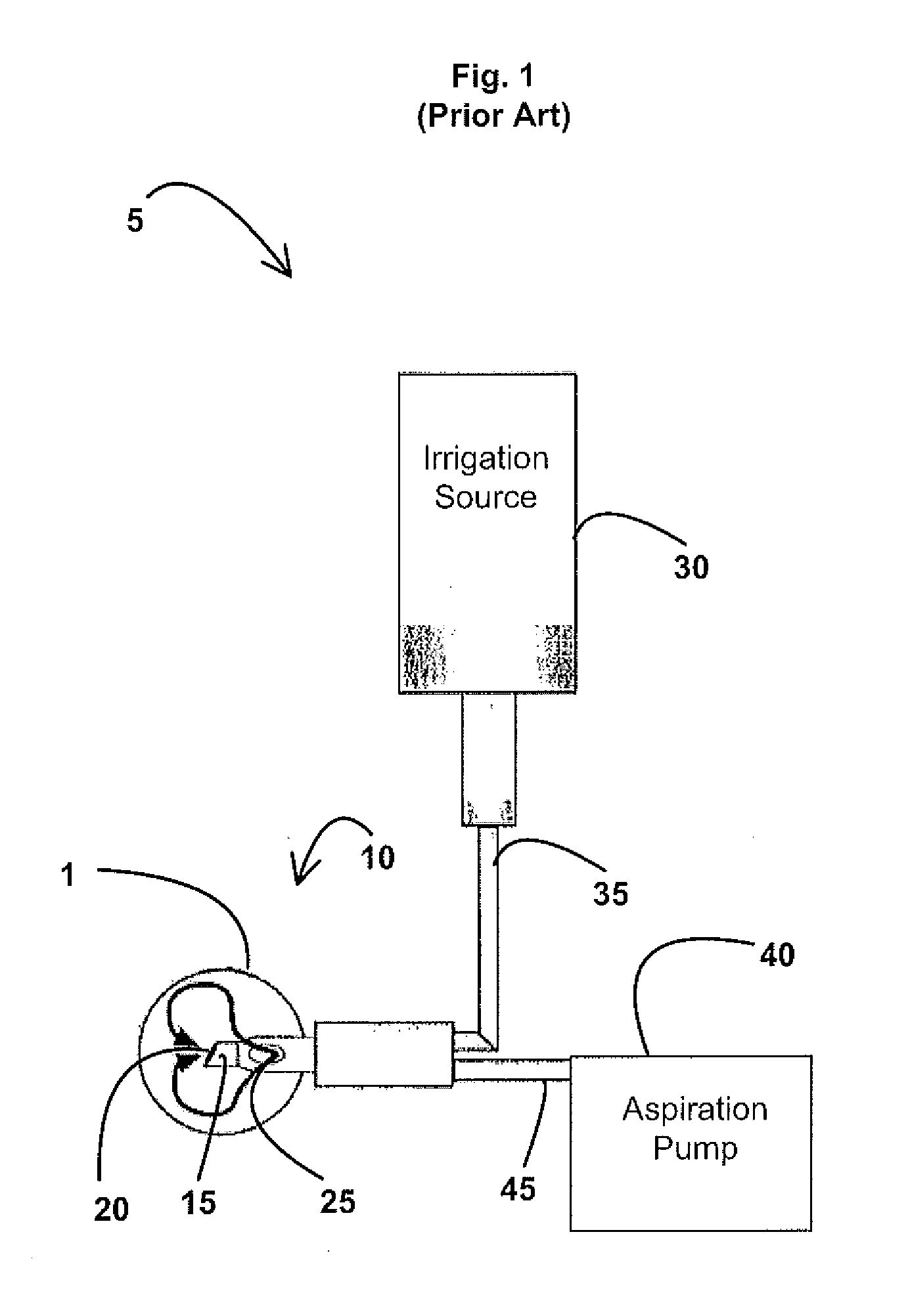
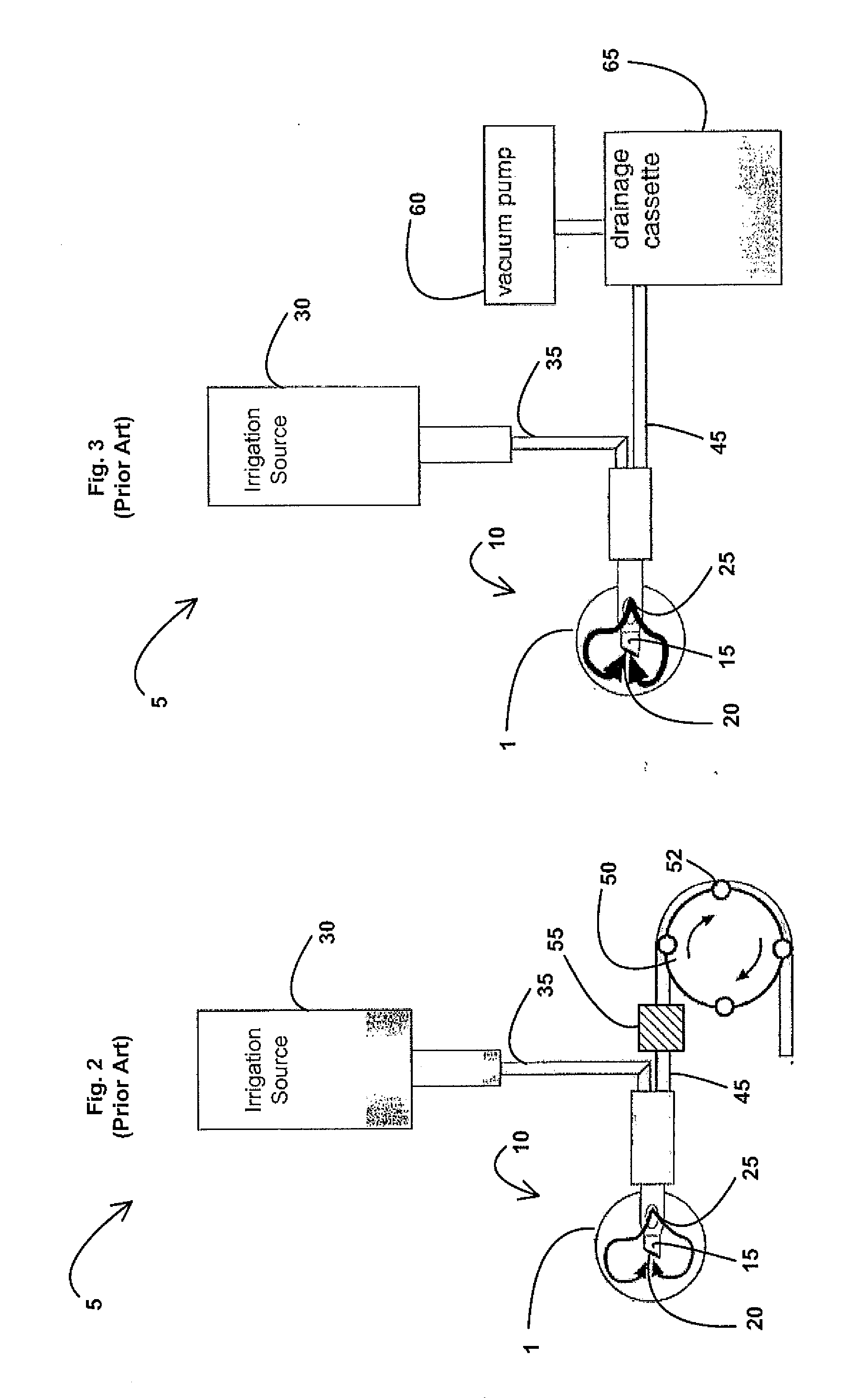
In the case of volumetric flow based pumps, this blockage can result in increased vacuum (i.e. increasingly negative pressure) in the aspiration line 45 and the longer the occlusion is in place, the greater the vacuum.
In contrast, with a vacuum-based pump, this blockage can result in a volumetric fluid flow drop off near the aspiration port 20.
Such post-occlusion surge events may lead to eye trauma.

Method used


Image

  • Systems and methods for power and flow rate control
  • Systems and methods for power and flow rate control
  • Systems and methods for power and flow rate control

Examples


Embodiment Construction

[0024]What are described below are preferred embodiments of aspiration systems using vacuum-based pumps, which can be applied to any system, medical (such as phacoemulsification, wound drainage, blood circulation, dialysis, or similar), or non-medical.

[0025]Variable Flow Restrictors

[0026]In general, the rate of fluid flow is a function of three (3) basic parameters: (1) the effective viscosity of the fluid, (2) the operative or driving vacuum level, and (3) the instantaneous effective resistance of the fluid transport pathway (e.g., aspiration line 45). For many surgical procedures, a constant effective viscosity can be assumed particularly if the fluid is predominantly a known irrigation source), and further, the operative or driving vacuum level can be easily measured and adjusted in an open-loop pressure monitoring system; however, for current aspiration systems with vacuum based pumps, the instantaneous effective resistance of the fluid transport pathway is a parameter that can ...


PUM


Abstract

The invention is generally directed to systems and methods for fluid control, and more particularly to systems and methods for power and flow rate control for aspiration. In accordance with one embodiment, an aspiration system includes an aspiration line having distal and proximal ends and an aspiration port defined in the distal end; a fluid transport device operatively coupled to the proximal end of the aspiration line; and a flow restrictor operatively coupled to the aspiration line in between the fluid transport device and the aspiration port. To measure occlusion within the line, first and second pressure sensors are utilized, the first sensor being operatively coupled to the aspiration line between the port and the restrictor and the second sensor being operatively coupled to the aspiration line between the restrictor and the fluid transport device. The pressure differential between the two sensors can provide an indication of the onset, presence, and / or elimination of an occlusion.

Description

FIELD OF THE INVENTION[0001]The field of the invention relates to systems and methods for fluid control, and more particularly to systems and methods for power and flow rate control.BACKGROUND OF THE INVENTION[0002]A number of medically recognized techniques are utilized for cataractic lens removal based on, for example, phacoemulsification, mechanical cutting or destruction, laser treatments, water jet treatments, and so on.[0003]The phacoemulsification method includes making a corneal incision and the insertion of a phacoemulsification handpiece which includes a needle that is ultrasonically driven in order to emulsify, or liquefy, the lens. A phacoemulsification system 5 known in the art is shown in FIG. 1. The system 5 generally includes a phacemulsification handpiece 10 coupled to an irrigation source 30 and an aspiration pump 40. The handpiece 10 includes a distal tip 15 (shown within the anterior chamber of the patient's eye 1) that emits ultrasonic energy to emulsify the cat...

Claims


Application Information

Patent Timeline
Patent Type & Authority Applications(United States)
IPC IPC(8): A61F9/007
CPCA61B2017/00084A61F9/00736A61M1/0035A61M1/0058A61M1/0031A61M1/743A61M1/74A61M1/77
Inventor GERG, JAMESREISIN, CARINA
Owner JOHNSON & JOHNSON SURGICAL VISION INC
Why Eureka
Eureka Blog
Learn More