
Automatic tooth movement measuring method employing three dimensional reverse engineering technique

a technology of reverse engineering and automatic tooth movement, which is applied in the direction of impression caps, instruments, teeth cappings, etc., can solve the problems of wasting material, affecting the quality of teeth,

Inactive Publication Date: 2008-05-29
GANGNEUNG WONJU NAT UNIV IND ACAD COOPERATION GROUP
View PDF3 Cites 42 Cited by
  • Summary
  • Abstract
  • Description
  • Claims
  • Application Information

AI Technical Summary

Benefits of technology

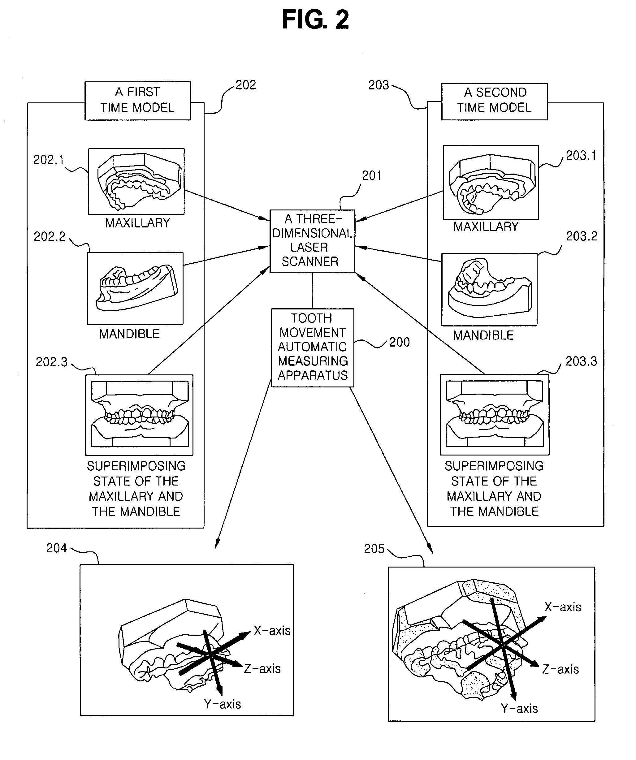
[0011]It is still another object of the present invention to provide a method which does not require a patient to be exposed to a huge amount of irradiation such as measuring by a lateral cephalometry or a tomography in measuring the movement of teeth. In other words, to provide a method which quantitatively and qualitatively measures the movement of teeth by applying space coordinates to the three dimensional digital model by a laser beam scanning.

Problems solved by technology

The impression taking process can cause lot of clinical problems such as waste of material, cross infection during the impression taking process, possibility of damage of a produced model, and storage.
However, as the prior art is a technique for manufacturing an orthodontic brace (brackets), the technique does not describe about a tooth movement measuring method by comparison of a superposition of a maxilla and a mandible at all.
However, with the present three dimensional measuring system, that the measurement at a certain moment only is possible, especially, setting a reference line, a reference plane, or a reference space for three dimensionally measuring a change of an anatomic structure such as a maxilla or a mandible is impossible and that there has been no development in a method for automating the setting process are regarded as biggest obstacles.
The method using X-ray can cause lot of clinical problems that a patient gets lots of radioactive doses and is imposed of financial burden and that it is complicated in operation as well as problems of efficiency and accuracy.
Still, an error generated in performing a measuring process of a three dimensional structure as a two dimensional planar measurement process is indicated as a huge obstacle in diagnosis and prognosis judgment.

Method used


Image

  • Automatic tooth movement measuring method employing three dimensional reverse engineering technique
  • Automatic tooth movement measuring method employing three dimensional reverse engineering technique
  • Automatic tooth movement measuring method employing three dimensional reverse engineering technique

Examples


Embodiment Construction

[0032]Hereinafter, preferred embodiments of the present invention are described in detail with respect to the accompanying drawings.

[0033]Before describing the embodiments of the present invention, the terms and words used in the specification and claims must not be interpreted in their usual or dictionary sense, but are to be interpreted as broadly as is consistent with the technical thoughts of the invention disclosed herein based upon the principle that the inventor can define the concepts of the terms properly in order to explain the invention in the best way.

[0034]Accordingly, the embodiments described in this specification and the construction shown in the drawings are nothing but one preferred embodiment of the present invention, and it does not cover all the technical ideas of the invention. Thus, it should be understood that various changes and modifications may be made upon the point of time of this application.

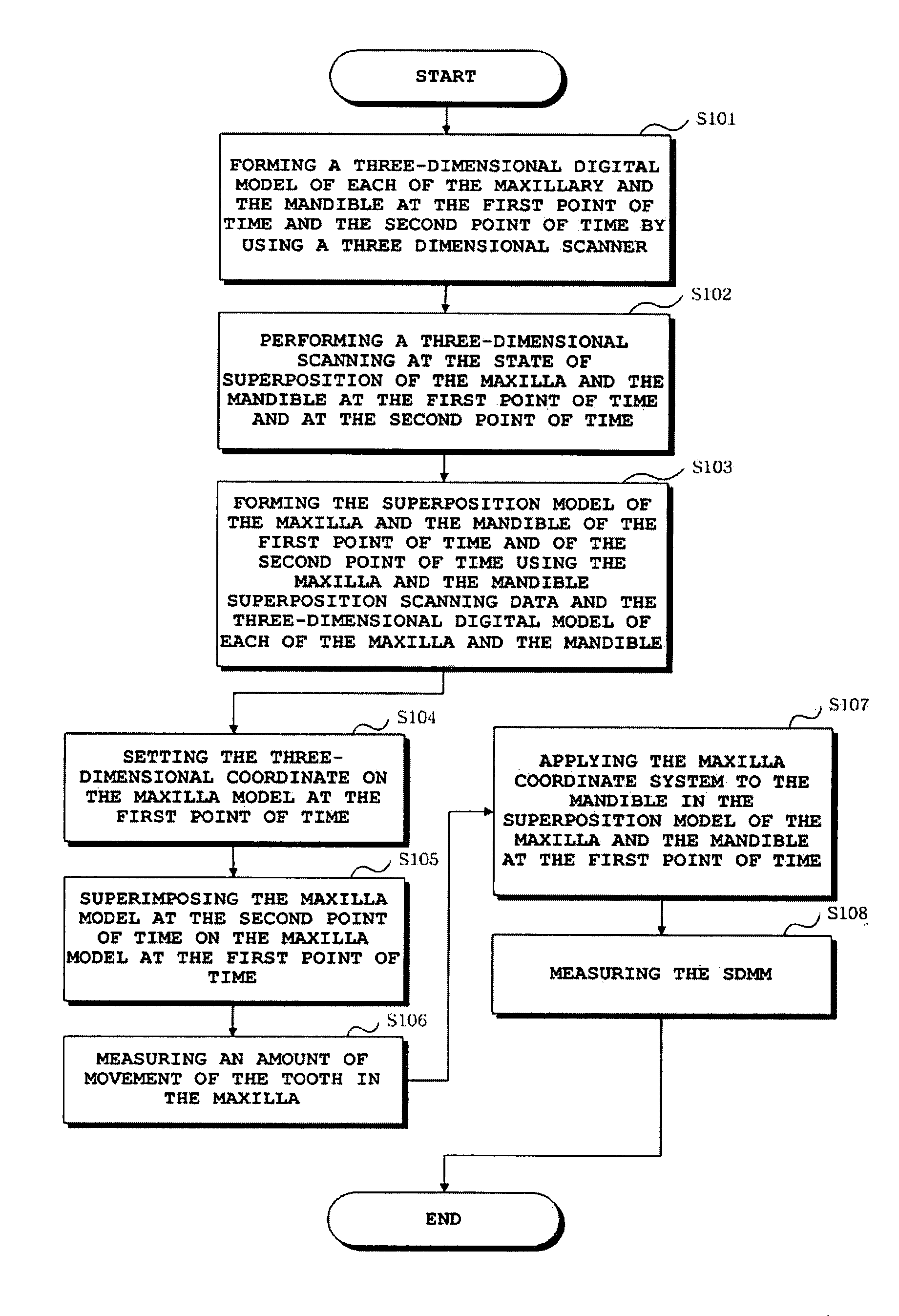
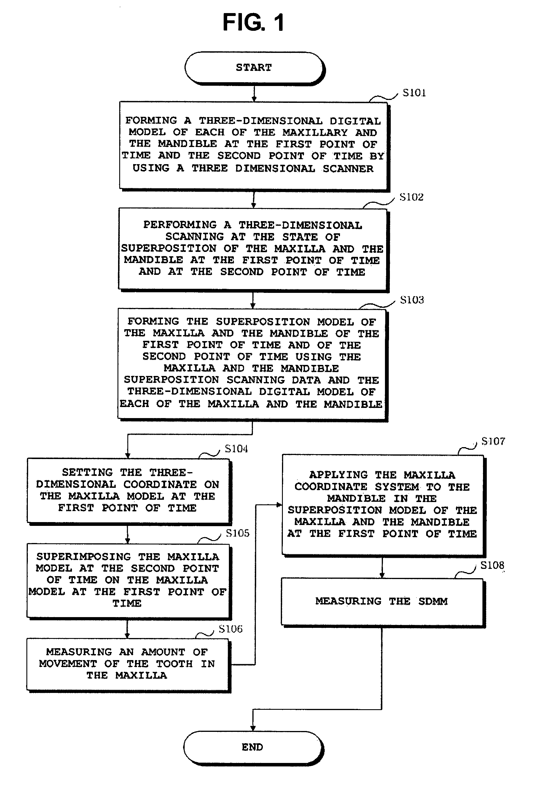
[0035]FIG. 1 is a flowchart showing an automatic tooth movemen...


PUM


Abstract

The present invention relates to an automatic tooth movement measuring method employing a three dimensional reverse engineering technique; and, more particularly, to an automatic tooth movement measuring method employing three dimensional reverse engineering technique, wherein a tooth movement measuring device capable of measuring a movement status of teeth before and after orthodontic treatment by spatially coordinating a three dimensional digital model of the tooth. According to the present invention, the tooth movement measuring device forms two three dimensional models which change corresponding to the point of time and applies a space coordinate to each model. And, by applying a technique superimposing each model, the tooth movement can be measured quantitatively and qualitatively. And, in accordance with the present invention, the tooth movement measuring device is capable of quantitatively and qualitatively measuring the tooth movement by applying space coordinates to the three dimensional digital model by a laser beam scanning without requiring a patient to be exposed to a huge amount of irradiation by such as a computer tomography in measuring the movement of teeth.

Description

FIELD OF THE INVENTION[0001]The present invention relates to an automatic tooth movement measuring method employing a three dimensional reverse engineering technique; and, more particularly, to an automatic tooth movement measuring method employing three dimensional reverse engineering technique, wherein a tooth movement measuring device capable of measuring a movement status of teeth before and after orthodontic treatment by spatially coordinating a three dimensional digital model of the tooth.DESCRIPTION OF RELATED ART[0002]A three dimensional reverse engineering technique is generating a virtual three dimensional digital model after coordinating in a three dimensional space in a computer by scanning using a three dimensional scanner. This means making a conventional orthodontic impression taking process into a data capable of processing by computerizing.[0003]In dental medical fields, especially in an area of orthodontics, three dimensionally reproducing an anatomic maxillary or ...

Claims


Application Information

Patent Timeline
IPC IPC(8): A61C11/00A61C19/045G06F17/00
CPCA61C7/00A61C2007/004A61C9/004A61C7/002A61C9/0053A61C19/04A61C19/00
Inventor CHA, BONG-KUEN
Owner GANGNEUNG WONJU NAT UNIV IND ACAD COOPERATION GROUP
Learn More