
Droplet Microreactor

a micro-reactor and droplet technology, applied in the field of droplet micro-reactors, can solve the problems of user toxicity, difficult to prevent dead volumes, and difficult to use, and achieve the effect of convenient purification and inexpensive fabrication

Inactive Publication Date: 2008-05-29
COMMISSARIAT A LENERGIE ATOMIQUE ET AUX ENERGIES ALTERNATIVES +1
View PDF4 Cites 288 Cited by
  • Summary
  • Abstract
  • Description
  • Claims
  • Application Information

AI Technical Summary

Benefits of technology

[0052]they can be functionalized and can therefore be used as soluble supports with a high specific charge and make it possible to carry out reactions with the same reactivity as in an aqueous or organic solution;
[0164]Furthermore, the microsystem of the present invention is a microsystem that is inexpensive to fabricate and compatible with an aggressive chemical environment, in particular due to the solvents used, the working temperatures, the pressures, etc.

Problems solved by technology

However, these Microsystems generate a certain number of problems: the channels become easily blocked, they are subject to load losses in the hydrodynamic mode, for example when syringe-pumps and pumps are used, and it is often difficult to prevent dead volumes and to optimize a low-cost microsystem compatible with an aggressive chemical environment, in particular by virtue of the solvents used, the working temperatures, the pressures, etc.
However, in both cases, the authors are confronted with the evaporation of these solvents, which, at best, implies the need for a cover or, at worst, makes them impossible to use.
In the case of organic solvents, the users are confronted with the problem of toxicity, for example by inhalation, of safety, for example due to risks of inflaming, and also with recycling.
(i) On insoluble supports:reactions in a heterogeneous medium have kinetics that are generally slower than in solution;sometimes certain reactions which are feasible in solution do not function on a solid support; andthe reactions are difficult to monitor.
(ii) On soluble polymer supports:the purification of the reaction products is very tricky,parallelization is difficult,low specific charge, andrecycling is difficult.

Method used


Image

  • Droplet Microreactor
  • Droplet Microreactor
  • Droplet Microreactor

Examples


example 1

Implementation of the Method of the Present Invention with Displacement of the Droplets so as to Carry Out a Series of Several Chemical Reactions: in the Case of the Grieco Reaction

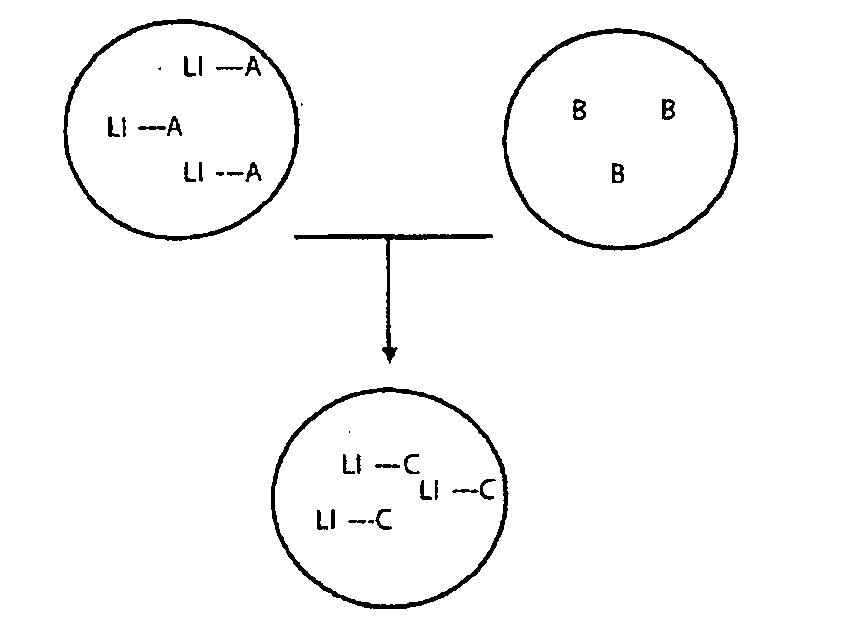
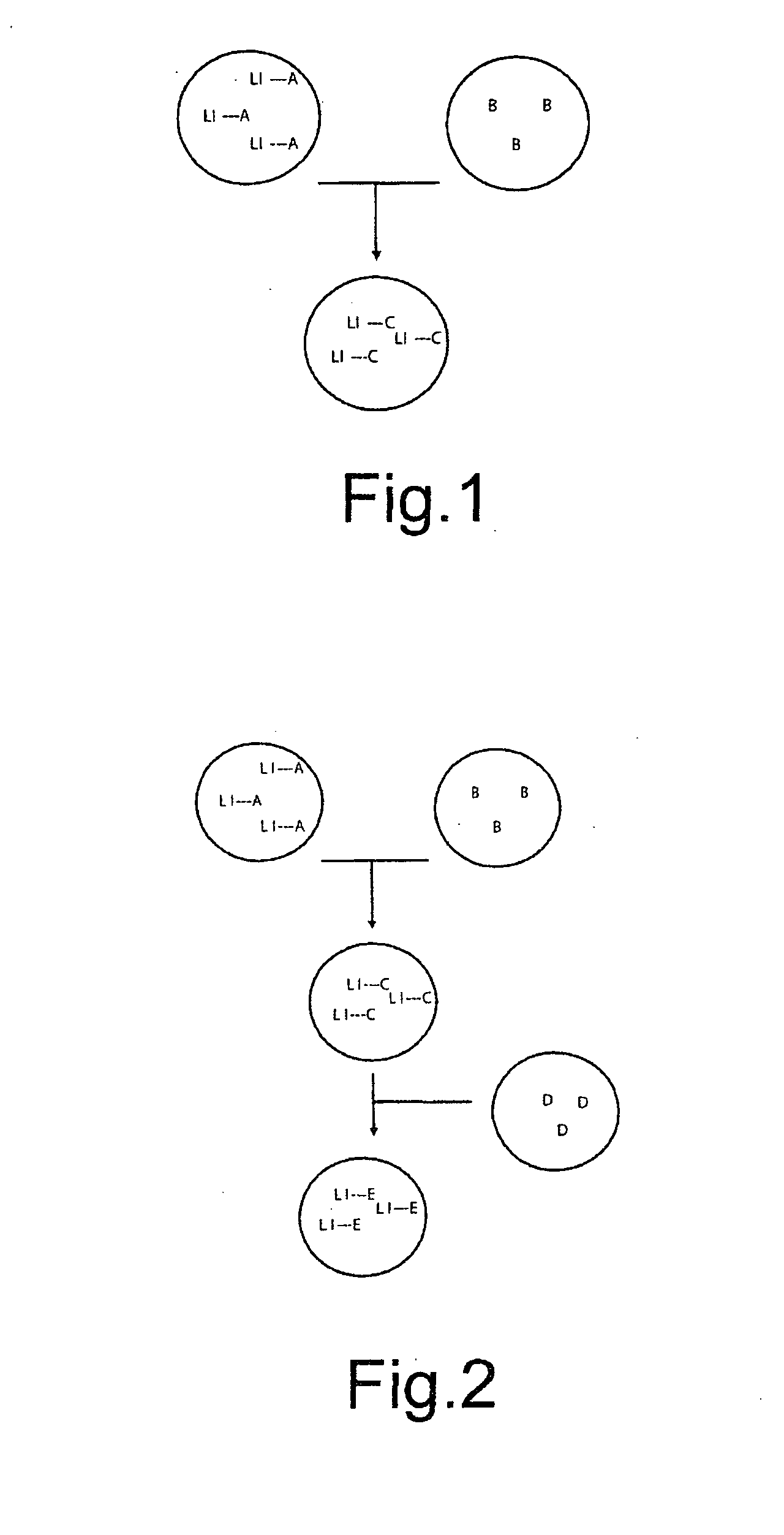
[0174]Three droplets of ionic liquids, each having a volume of 0.5 μl, are deposited onto a Teflon-coated surface of the reaction chamber described in document [16] and represented schematically in the attached FIGS. 3 and 6.

[0175]The droplets used in this example have the following composition:[0176]droplet 1: droplet of 4-aminobenzoic acid supported on ammonium salt 1 (see reaction scheme below) in a 1 M solution in [tmba] [NTf2][0177]droplet 2: droplet of 2 equivalents of 4-nitro-benzaldehyde and 1.2 equivalents of TFA in a 0.5 M solution in [tmba][NTf2]; and[0178]droplet 3: droplet of 10 equivalents of indene in a 1 M solution in [tmba][NTf2].

[0179]The droplet displacement technique used in this example is an electrowetting displacement technique which operates as represented schematically in FIG. 6 (...

example 2

Detritylation Reaction Carried Out According to the Method of the Present Invention

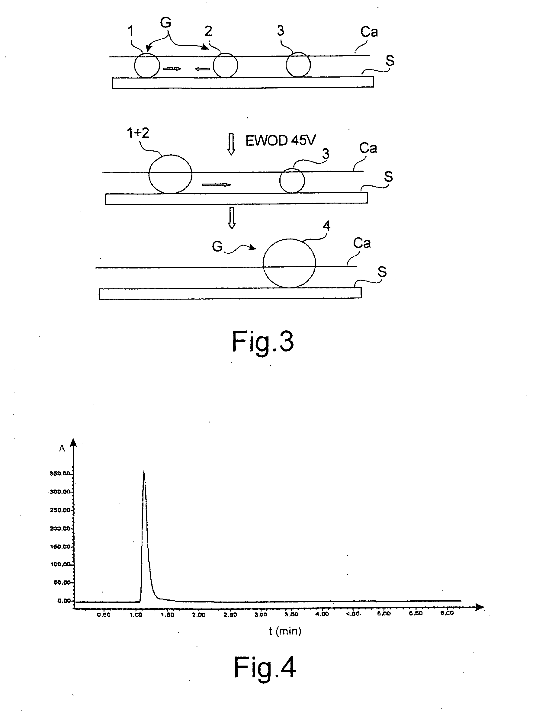
[0202]Two droplets of matrix ionic liquid ([btma] [NTf2]), each of 0.5 μl, are deposited on the Teflon-coated surface of the reaction chamber described in document [16].

[0203]Each of the droplets contains a reagent: droplet No. 1 contains a tritylated thymidine base and droplet No. 2 contains dichloroacetic acid.

[0204]Droplet No. 1 is made to converge towards the other droplet using the electrowetting technique. The voltage applied is 45 V.

[0205]After fusion of the two droplets, the mixture is incubated at ambient temperature for 5 minutes. An orangey coloration of the droplet demonstrates the formation of the desired product.

[0206]The chemical reaction carried out is the following:

[0207]In which DCA is dichloroacetic acid and EWOD represents the displacement by electrowetting.

example 3

Implementation of an Enzymatic Reaction

[0208]A first reaction mixture is prepared as follows: 50 mM citrate-phosphate buffer, pH 6.5 (10 ml), o-phenylene-diamine (OPD, 20 mg) and aqueous hydrogen peroxide (4 μl).

[0209]A droplet of this mixture, 0.5 μl in volume, is dissolved in matrix ionic liquid ([btma] [NTf2]) (0.5 μl).

[0210]A second reaction mixture is prepared as follows: matrix ionic liquid ([btma] [NTf2]) (0.9 μl) and horseradish peroxidase (0.1 μl at 20 μm).

[0211]A droplet (0.5 μl) of each of the mixtures is deposited onto the Teflon-coated surface of the reaction chamber used in Examples 1 and 2 above.

[0212]Droplet No. 2 is made to converge towards the other droplet using the electrowetting technique. The voltage applied is 45 V.

[0213]After fusion of the two droplets, the mixture is incubated at ambient temperature for 20 minutes.

[0214]A brown coloration characteristic of the enzymatic reaction for forming 2,3-diaminophenazine is observed.

Example 4

Implementation of the Meth...


PUM


Abstract

The present invention relates to a droplet microreactor, i.e. a microreactor consisting of a droplet of a specific liquid, the microreactor being wall-less, wherein the interface of the specific liquid with the ambient environment and with the support on which the droplet is deposited defines the limits of the microreactor. The microreactor is characterized in that it consists of a droplet comprising at least one ionic liquid. The present invention also relates to methods for carrying out chemical or biochemical reactions and / or mixes using said droplet microreactor, and also to a lab-on-chip comprising a microreactor according to the invention.

Description

TECHNICAL FIELD[0001]The present invention relates to a droplet microreactor, i.e. to a microreactor consisting of a droplet of a specific liquid, the microreactor being wall-less, wherein the interface of the specific liquid with the ambient environment and with the support on which the droplet is deposited defines the limits of the microreactor.[0002]The present invention also relates to methods for carrying out chemical or biochemical reactions and / or mixes using said droplet microreactor, and also to a lab-on-chip comprising a microreactor according to the invention.[0003]The specific liquid used in the present invention is an ionic liquid or a mixture of ionic liquids.[0004]The present invention finds numerous applications, in particular in lab-on-chips where very small volumes of reaction media are generally used. It makes it possible, for example, to carry out syntheses on a soluble support, parallel syntheses, convergent syntheses, or immobilizations on the ionic liquids of ...

Claims


Application Information

Patent Timeline
IPC IPC(8): B01J19/00B65D47/18B01F15/02B01J14/00B01L3/00B01L99/00G01N27/447
CPCB01F13/0071C12P17/12B01J14/00B01J19/0093B01L3/502792B01L2300/0816B01L2300/089B01L2400/0406B01L2400/0415B01L2400/0427B01L2400/0433B01L2400/0442B01L2400/0487G01N2035/1046C07C41/14C07C227/16C07D221/18B01F13/0076B01F33/3021B01F33/3031
Inventor MARCHAND, GILLESVINET, FRANCOISEDELAPIERRE, GUILLAUMEHASSINE, FATIMAGMOUH, SAIDVAULTIER, MICHEL
Owner COMMISSARIAT A LENERGIE ATOMIQUE ET AUX ENERGIES ALTERNATIVES
Learn More