Television image receiver

a receiver and television technology, applied in the field of television image receivers, can solve the problems of increased relative humidity, condensation, water vapor entering the outside of the cabinet, etc., and achieve the effect of suppressing the occurrence of condensation inside the cabinet and keeping air tight outdoors

Inactive Publication Date: 2008-05-29
SANYO ELECTRIC CO LTD
View PDF3 Cites 27 Cited by
  • Summary
  • Abstract
  • Description
  • Claims
  • Application Information

AI Technical Summary

Benefits of technology

[0010]With the above-described structure, the present invention has the following effects:
[0011]Although change in pressure inside the cabinet can be controlled by the internal pressure regulating valve, the internal pressure regulating valve may cause the entrance of water vapor from outside the cabinet. When the temperature outside the cabinet is decreased, relative humidity is increased, and therefore, condensation is likely to occur.
[0013]In this manner, the combination of the moisture adjuster and the internal pressure regulating valve can keep air tightness outdoors for a long period of time, and further, can suppress the occurrence of condensation inside the cabinet for a long period of time.
[0014]Since the metallic rear frame having the fin disposed therein is exposed outward, heat radiated from the inside of the rear cabinet can be radiated outward even if the rear cabinet is tightly sealed with the rear frame and the sealing plate. Moreover, since the rear cabinet is tightly sealed, water or the like also can be prevented from entering the rear cabinet.

Problems solved by technology

Although change in pressure inside the cabinet can be controlled by the internal pressure regulating valve, the internal pressure regulating valve may cause the entrance of water vapor from outside the cabinet.
When the temperature outside the cabinet is decreased, relative humidity is increased, and therefore, condensation is likely to occur.

Method used


Image

  • Television image receiver
  • Television image receiver
  • Television image receiver

Examples


Embodiment Construction

[0031]One preferred embodiment according to the present invention will be described in detail below with reference to the attached drawings.

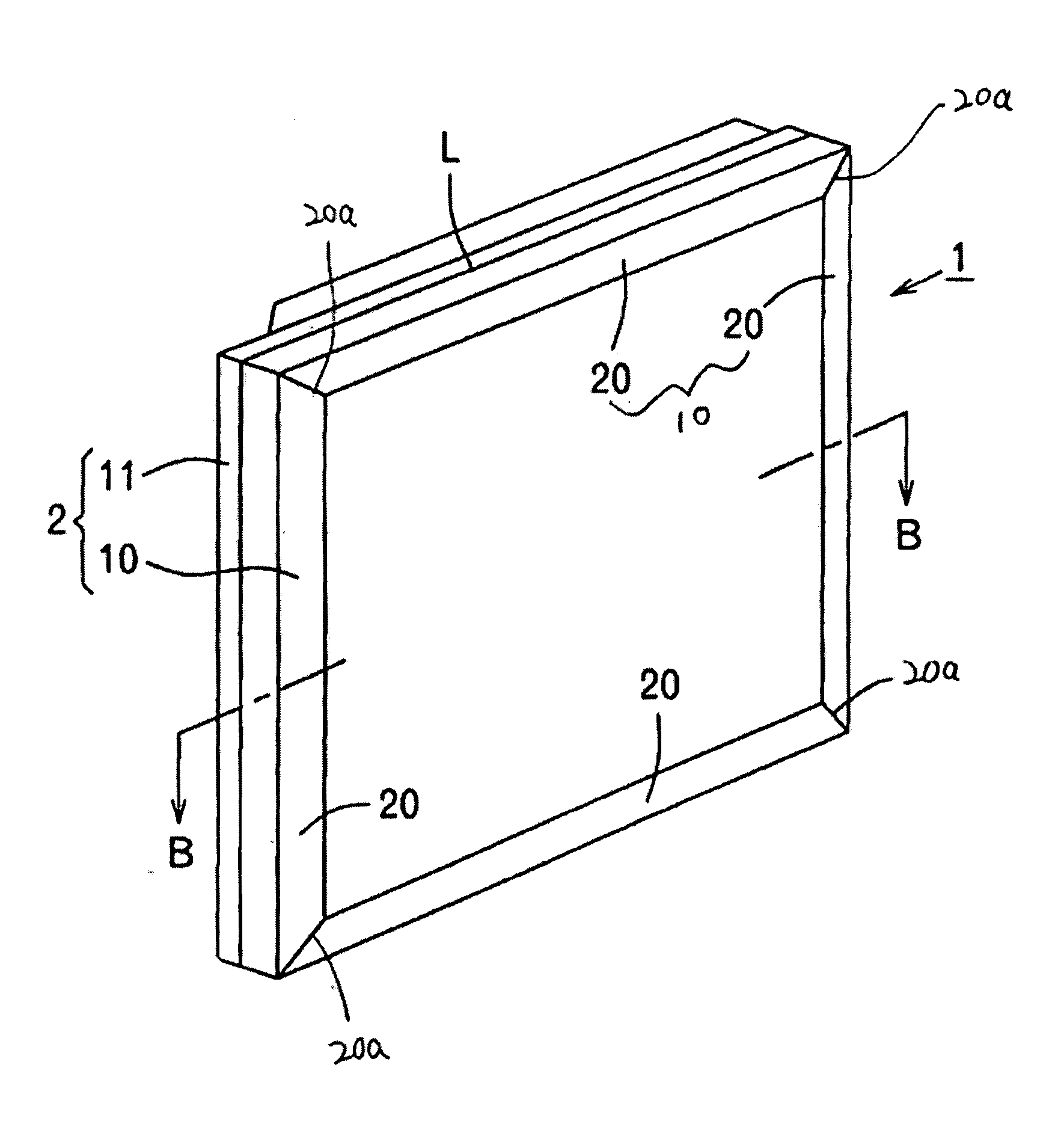
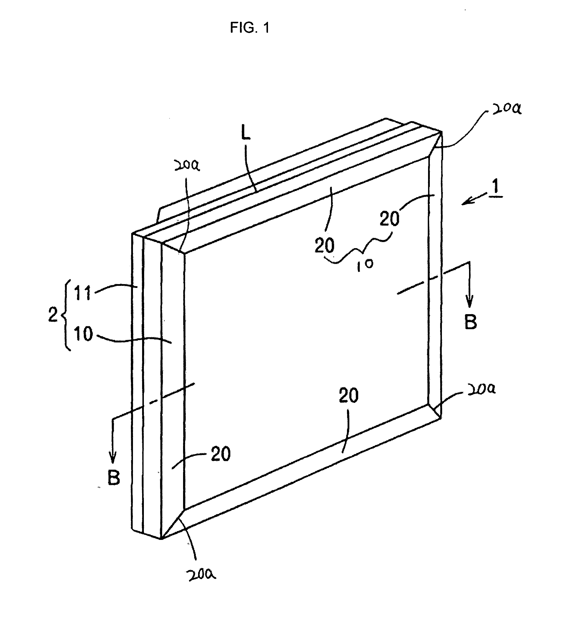
[0032]FIG. 1 is a perspective view showing a television image receiver (1) according to the present embodiment, as viewed from the front; FIG. 2 is a perspective view showing the television image receiver according to the present embodiment, as viewed from the back; and FIG. 3 is a back view showing the television image receiver according to the present embodiment. The television image receiver (1) includes a cabinet (2) serving as an outward appearance part, which is constituted of a fore cabinet (10) having an image receiver such as a liquid crystal panel or a plasma display panel disposed therein and a rear cabinet (11) for radiating heat from the inside. A demarcation line defined between both of the cabinets (10) and (11) is designated by reference character L in FIGS. 1 and 2.

[0033]The rear cabinet (11) includes a metallic rear frame (3) h...


PUM


Abstract

A television image receiver (1) includes: an internal pressure regulating valve (5) provided above a tightly sealed cabinet (2), for allowing ventilation inside and outside the cabinet (2); and moisture adjusters (7), each having a moisture absorbing function, fixed inside the cabinet (2). The internal pressure regulating valve (5) includes a ventilation filter (6), which allows air and water vapor to pass therethrough but prevents water from permeating therethrough, inside a valve body (50). The internal pressure regulating valve (5) alleviates change in pressure inside the cabinet (2). Water vapor outside the cabinet (2) enters the cabinet (2) through the internal pressure regulating valve (5). When a temperature inside the cabinet (2) is decreased, the moisture adjuster (7) absorbs the water vapor to decrease the relative humidity, thus preventing occurrence of condensation.

Description

BACKGROUND OF THE INVENTION[0001]1. Field of the Invention[0002]The present invention relates to a television image receiver, which may be used outdoors in an environment exposed to wind and rain.[0003]2. Description of the Related Art[0004]A television image receiver having a tightly sealed cabinet has been hitherto proposed on the assumption that the television image receiver is used in a damp environment such as a bathroom (see Japanese Laid-Open Patent Publication No. 2006-158096). A similar cabinet structure is also applied to a television image receiver, which is assumed to be used outdoors in an environment exposed to wind and rain.[0005]Since the cabinet is tightly sealed, and further, the television image receiver is used outdoors, pressure inside the cabinet is varied due to an abrupt change in temperature, which may cause damage on the cabinet. As a countermeasure against such a situation, a conceivable method is that an internal pressure regulating valve is disposed in t...

Claims


Application Information

Patent Timeline
Patent Type & Authority Applications(United States)
IPC IPC(8): H04N5/64
CPCH04N5/64G02F2001/133311H05K5/068H05K5/0213G02F1/133311H05K5/0212H05K5/0216
Inventor NAKAMICHI, MASAYASAKAKIBARA, MASANORI
Owner SANYO ELECTRIC CO LTD
Why Eureka
Try Eureka