Variable frequency clock output circuit and apparatus, motor driving apparatus, and image forming apparatus

a technology of variable frequency clock and output circuit, which is applied in the direction of generating/distributing signals, programme control, and dynamo-electric converter control, etc., can solve the problems of increased risk of loss of synchronism, difficulty in accelerating or decelerating a stepping motor to various target frequencies at different accelerations, and lack of versatility

Active Publication Date: 2008-05-29
KONICA MINOLTA BUSINESS TECH INC
View PDF13 Cites 2 Cited by
  • Summary
  • Abstract
  • Description
  • Claims
  • Application Information

AI Technical Summary

Benefits of technology

[0015]The preferred embodiments of the present invention have been developed in view of the above-mentioned and/or other problems i...

Problems solved by technology

A rough change in drive frequency at the time of accelerating/decelerating a stepping motor causes an increased risk of loss of synchronism (loss of synchronism between the control clock and the revolution) of the stepping motor.
The clock output circuit disclosed by the aforementioned Japanese Un...

Method used


Image

  • Variable frequency clock output circuit and apparatus, motor driving apparatus, and image forming apparatus
  • Variable frequency clock output circuit and apparatus, motor driving apparatus, and image forming apparatus
  • Variable frequency clock output circuit and apparatus, motor driving apparatus, and image forming apparatus

Examples


Embodiment Construction

[0077]In the following paragraphs, some preferred embodiments of the invention will be described by way of example and not limitation. It should be understood based on this disclosure that various other modifications can be made by those in the art based on these illustrated embodiments.

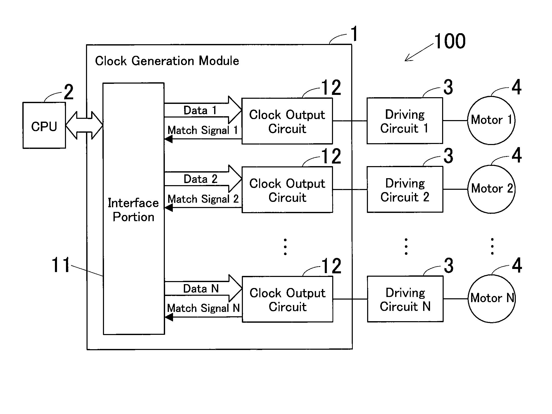
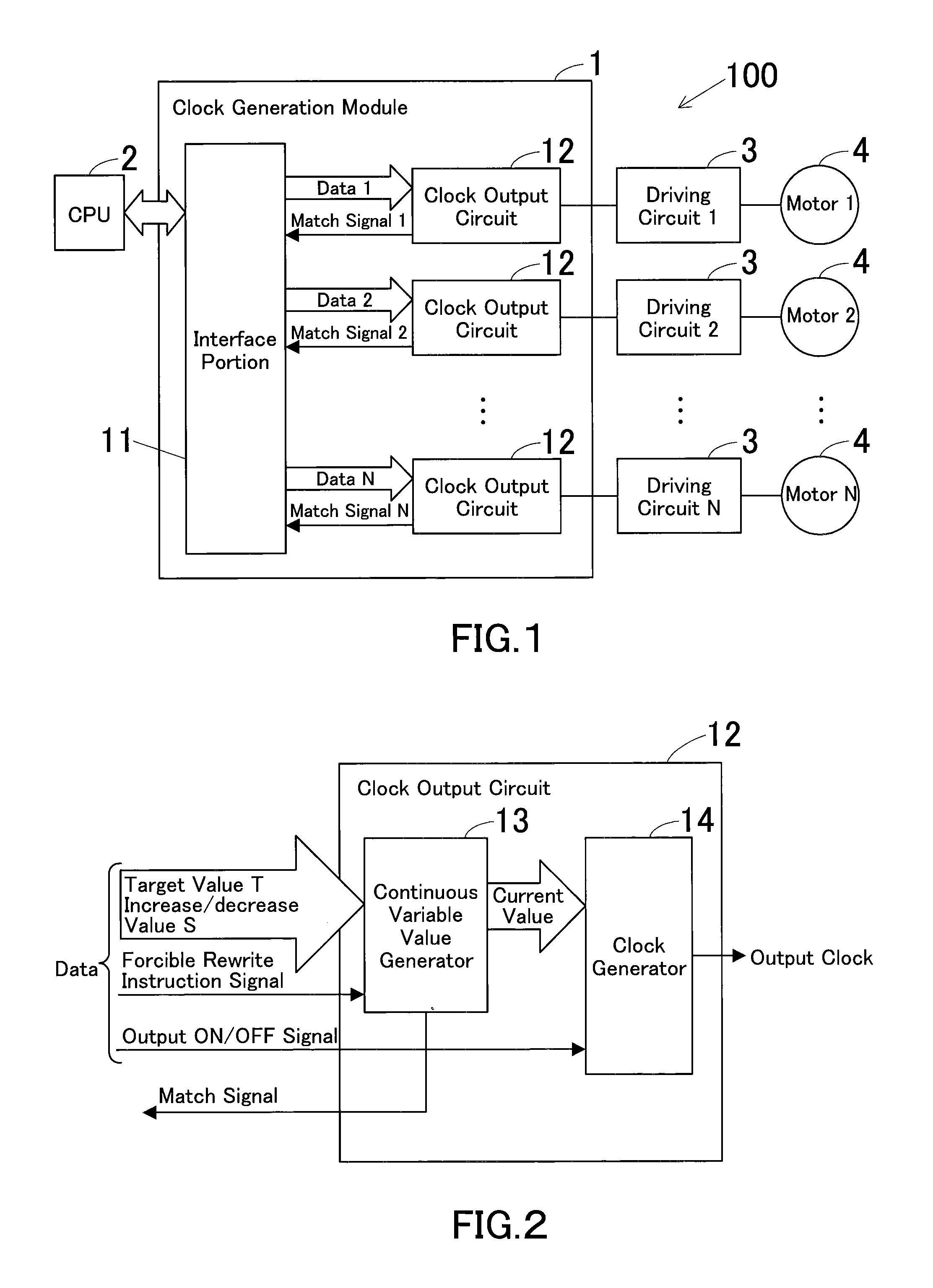
[0078]FIG. 1 is a block diagram showing a motor driving apparatus using a variable frequency clock output circuit (hereinafter simply referred to as “clock output circuit) according to an embodiment of the present invention.

[0079]This motor driving apparatus 100 is equipped with one clock generation module 1, one CPU 2 and one or a plurality of motor driving circuits 3. A plurality of motor driving circuits 3 perform a drive control of a plurality of motors 4.

[0080]The clock generation module 1 is a valuable frequency clock output apparatus (hereinafter simply referred to as a “clock output apparatus”) in which an interface portion 11 and one or a plurality of clock output circuits 12 are integrally ...


PUM


Abstract

A variable frequency clock output circuit, comprising: a target value register which stores a target value corresponding to an arbitrarily set target frequency; an increase/decrease value register which stores an arbitrarily set increase/decrease value; an adder-subtractor which has an input portion into which a current output value is inputted and outputs a calculation result obtained by adding/subtracting the increase/decrease value stored in the increase/decrease value register to/from the current output value inputted into the input portion based on an addition/subtraction instruction signal; a comparator which compares an output value of the adder-subtractor to the target value stored in the target value register, and outputs an addition/subtraction instruction signal to the adder-subtractor until the output value of the adder-subtractor and the target value coincide; and a clock generator which outputs a clock signal having a frequency proportional to the output value of the adder-subtractor.

Description

[0001]This application claims priority under 35 U.S.C. §119 to Japanese Patent Application No. 2006-322644 filed on Nov. 29, 2006, the entire disclosure of which is incorporated herein by reference in its entirety.BACKGROUND OF THE INVENTION[0002]1. Field of the Invention[0003]The present invention relates to, for example, a variable frequency clock output circuit and apparatus preferably used to accelerate / decelerate a paper conveyance motor or the like for use in image forming apparatuses. It also relates to a motor driving apparatus and an image forming apparatus.[0004]2. Description of the Related Art[0005]The following description sets forth the inventor's knowledge of related art and problems therein and should not be construed as an admission of knowledge in the prior art.[0006]For example, in image forming apparatuses, such as, e.g., MFP (Multi Function Peripherals) which are multifunction digital complex machines, a plurality of stepping motors are used to convey papers on ...

Claims


Application Information

Patent Timeline
IPC IPC(8): H03K3/00
CPCG05B2219/25399H02P8/00G06F1/08
Inventor TACHIBANA, YUTATAKAHASHI, KATSUNORIKASAMATSU, TORUTAMURA, TOMONOBUNAKANO, NORIHIKO
Owner KONICA MINOLTA BUSINESS TECH INC
Why Eureka
Try Eureka