Hunting and Sporting Firearm

Inactive Publication Date: 2008-05-29
FABBRICA DARMI PIETRO BERETTA SPA
View PDF23 Cites 3 Cited by
  • Summary
  • Abstract
  • Description
  • Claims
  • Application Information

AI Technical Summary

Benefits of technology

[0012]The aim of the present invention is, therefore, to overcome the above-mentioned disadvantages by provid

Problems solved by technology

It has been found, however, that on account of the extremely strong forces applied to the propulsion means by the elastic means, the stopping means are subjected to violent shocks which cause wear and which, in the long run, modify their position to such an extent as to prevent the firing pin from returning to its initial rest position, thereby giving rise to the problems described above.

Method used


Image

  • Hunting and Sporting Firearm
  • Hunting and Sporting Firearm
  • Hunting and Sporting Firearm

Examples


Embodiment Construction

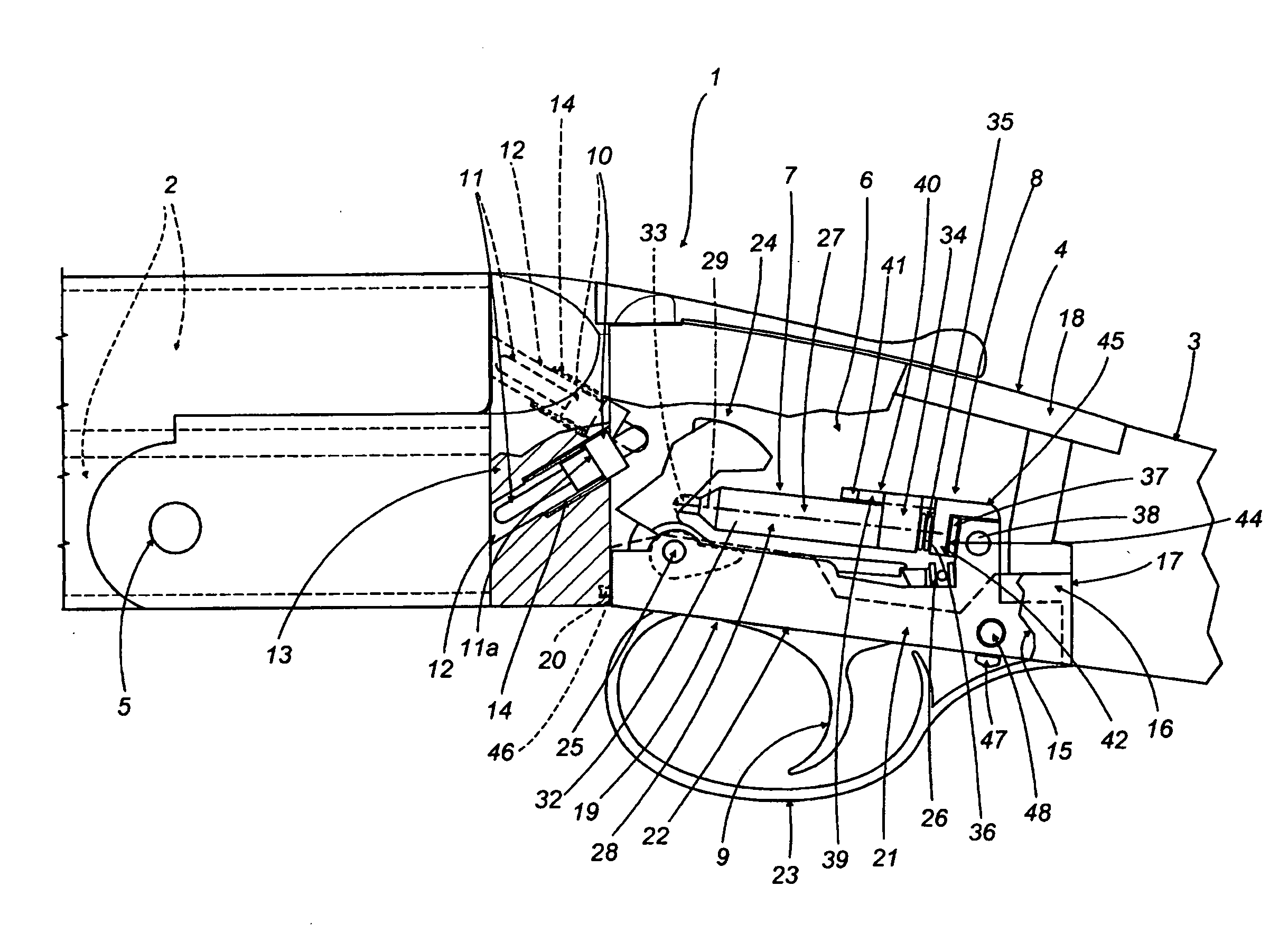
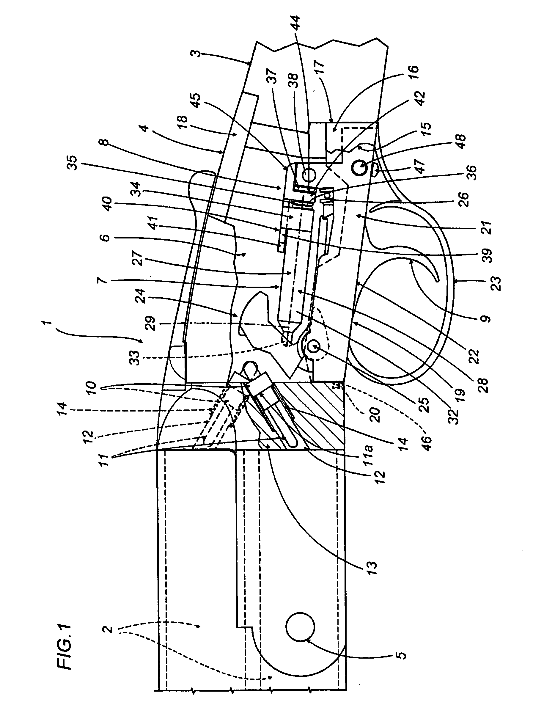
[0018]With reference to FIGS. 1 and 2, the numeral 1 denotes in its entirety an over-and-under firearm comprising a pair of barrels 2 (partially illustrated), and a stock 3 (partially illustrated), between which there is a rolling block 4 to which the barrels 2 are pivoted by means of a hinge pin 5.

[0019]The numeral 6 denotes a cavity in the rolling block 4, designed to accommodate a snap action mechanism 7 comprising, for each barrel 2, an action 8 which, upon being actuated by a trigger 9, causes a respective firing pin 10 associated with each barrel 2 to impact the case of a cartridge (not illustrated).

[0020]Each firing pin 10 consists of a substantially cylindrical rod 11 having a rim 11a at an intermediate position of it and housed in a through hole 12 made in a transversal wall 13 separating the cavity 6 from the respective barrel 2. Positioned around each firing pin 10 and abutting against the rim 11a there is a helical spring 14 for retracting the firing pin 10 into the cavi...


PUM


Abstract

In a hunting and sporting firearm including a rolling block having a cavity for accommodating at least one action, the latter comprising a hammer for actuating a firing pin, a propulsion element for propelling the hammer and a trigger, said propulsion element is subjected to the action of a shock absorber consisting of its own drive means constituted by a spiral spring.

Description

[0001]This invention relates to a hunting and sporting firearm.[0002]In particular, this invention relates to an action forming part of a firearm of this kind.[0003]The term “action” is used here to mean the combined parts of a percussion and firing mechanism which, upon actuation of the trigger, causes a firing pin to impact the cartridge primer so as to ignite the propellant.[0004]For simplicity, this specification will refer to a single-barrel firearm, although it will be understood that it also applies to double-barrel firearms (with side-by-side or over-and-under barrels).BACKGROUND OF THE INVENTION[0005]As is known, the action is mounted inside the rolling block, that is, the steel block attached to the stock and to which the barrels are pivoted. In a single-barrel firearm, the action comprises a hammer mounted on a transverse pin and designed to directly strike the firing pin of the cartridge primer, and means for propelling the hammer, consisting of snap action means actuate...

Claims


Application Information

Patent Timeline
IPC IPC(8): F41A19/00F41A19/15F41A19/54
CPCF41A19/54F41A19/15
Inventor DE GREGORIO, VITO
Owner FABBRICA DARMI PIETRO BERETTA SPA
Why Eureka
Try Eureka