
Watercraft steering device and watercraft

a steering device and watercraft technology, applied in the direction of steering initiation, special purpose vessels, vessel construction, etc., can solve the problems of poor operation feel, impaired responsiveness and poor operation feel, etc., to achieve lighter operation feel of steering wheel, respond quickly, and increase the deflection torque

Active Publication Date: 2008-05-22
YAMAHA MOTOR CO LTD
View PDF67 Cites 6 Cited by
  • Summary
  • Abstract
  • Description
  • Claims
  • Application Information

AI Technical Summary

Benefits of technology

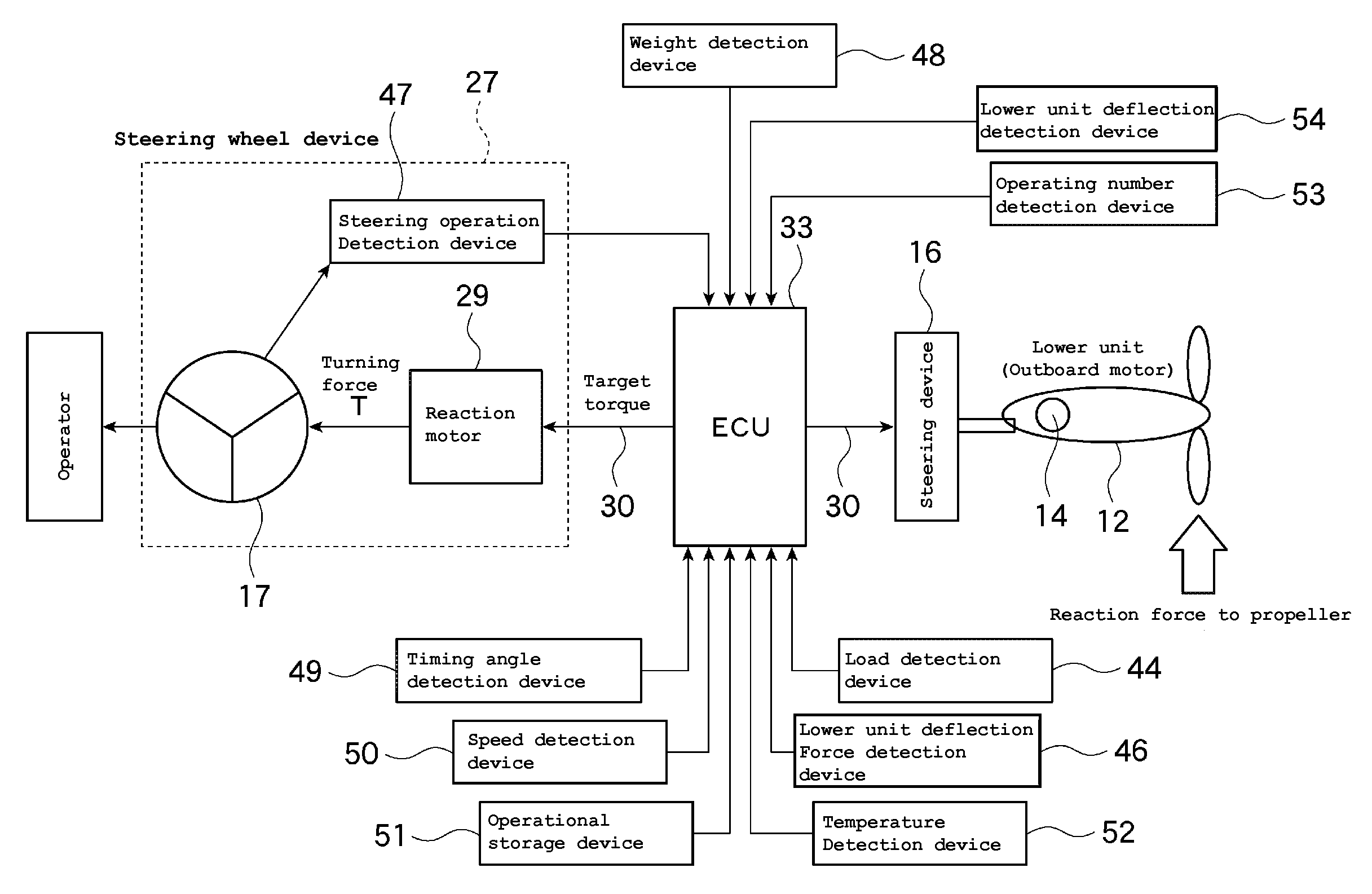
The patent text describes a steering system for watercraft that includes a steering device with an electric actuator. The system also includes a reaction actuator that applies a reaction force to the steering wheel. The system uses a torque computation device to compute a torque target value based on the detection of the watercraft's operation status and the status of the electric actuator. The reaction actuator control device controls the reaction actuator in accordance with the torque target value. The technical effect of this system is to provide a more responsive and comfortable steering experience for the operator, even when the watercraft is under external force or running at high speeds.

Problems solved by technology

Unfortunately, in the case where a larger output (a larger deflection torque) is required for steering, for example, when the steering wheel is operated faster, the steering motor (electric actuator) becomes less responsive, resulting in a poor operation feel.
In such case, a required lower unit deflection force may exceed the limit of the motor, resulting in impaired responsiveness and a poorer operation feel.
In such cases, since the motor characteristics at higher temperatures provide lower torque, a target lower unit deflection force required may not be obtained, resulting in impaired responsiveness and a poorer operation feel.

Method used


Image

  • Watercraft steering device and watercraft
  • Watercraft steering device and watercraft
  • Watercraft steering device and watercraft

Examples


Embodiment Construction

[0023]The figures illustrate a steering system for a watercraft configured in accordance with certain features, aspects, and advantages of at least one of the inventions described herein. The watercraft merely exemplifies one type of environment in which the present inventions can be used. However, the various embodiments of the steering systems disclosed herein can be used with other types of watercraft or other vehicles that benefit from improved steering control. Such applications will be apparent to those of ordinary skill in the art in view of the description herein. The present inventions are not limited to the embodiments described, which include the preferred embodiments, and the terminology used herein is not intended to limit the scope of the present inventions.

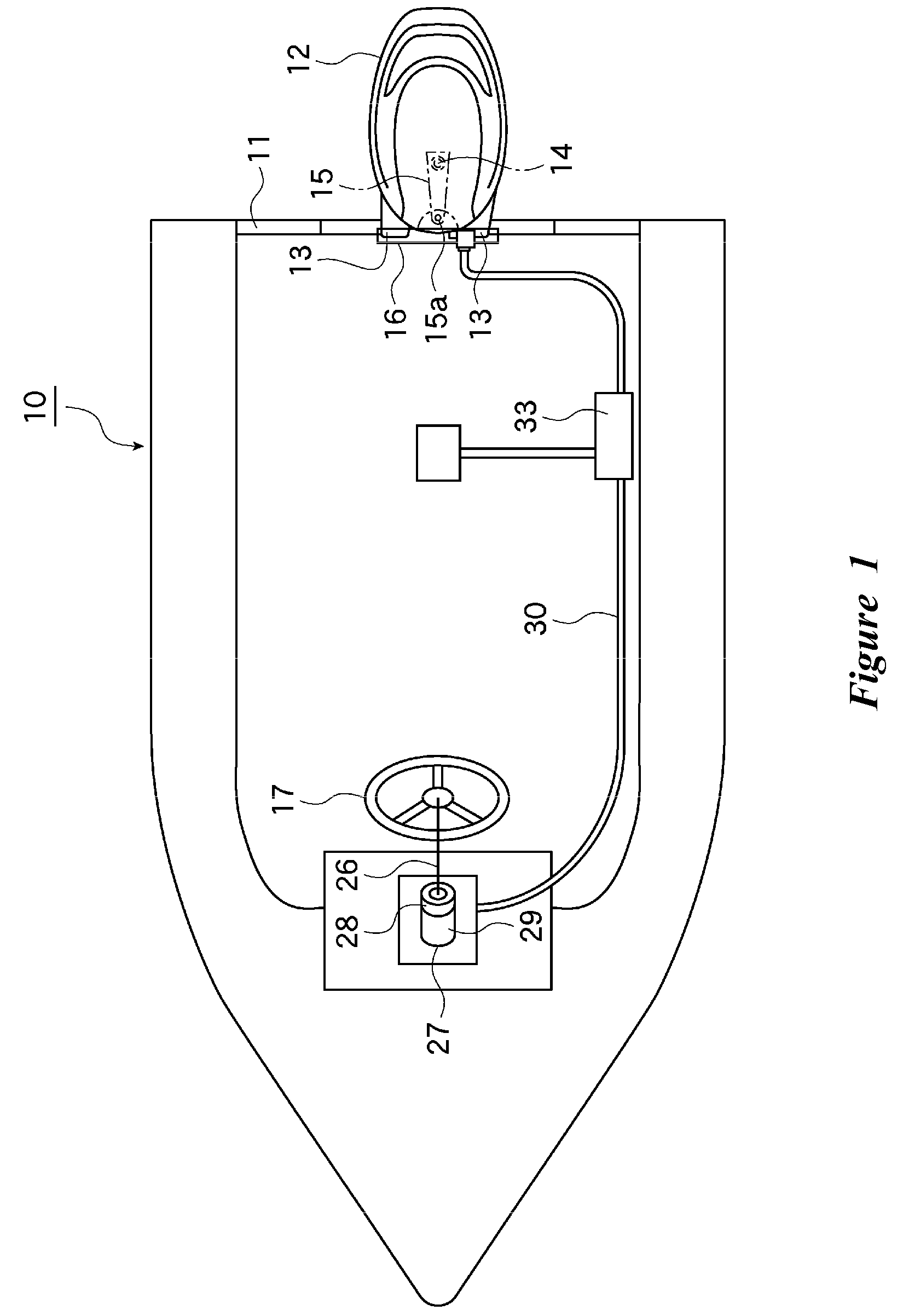
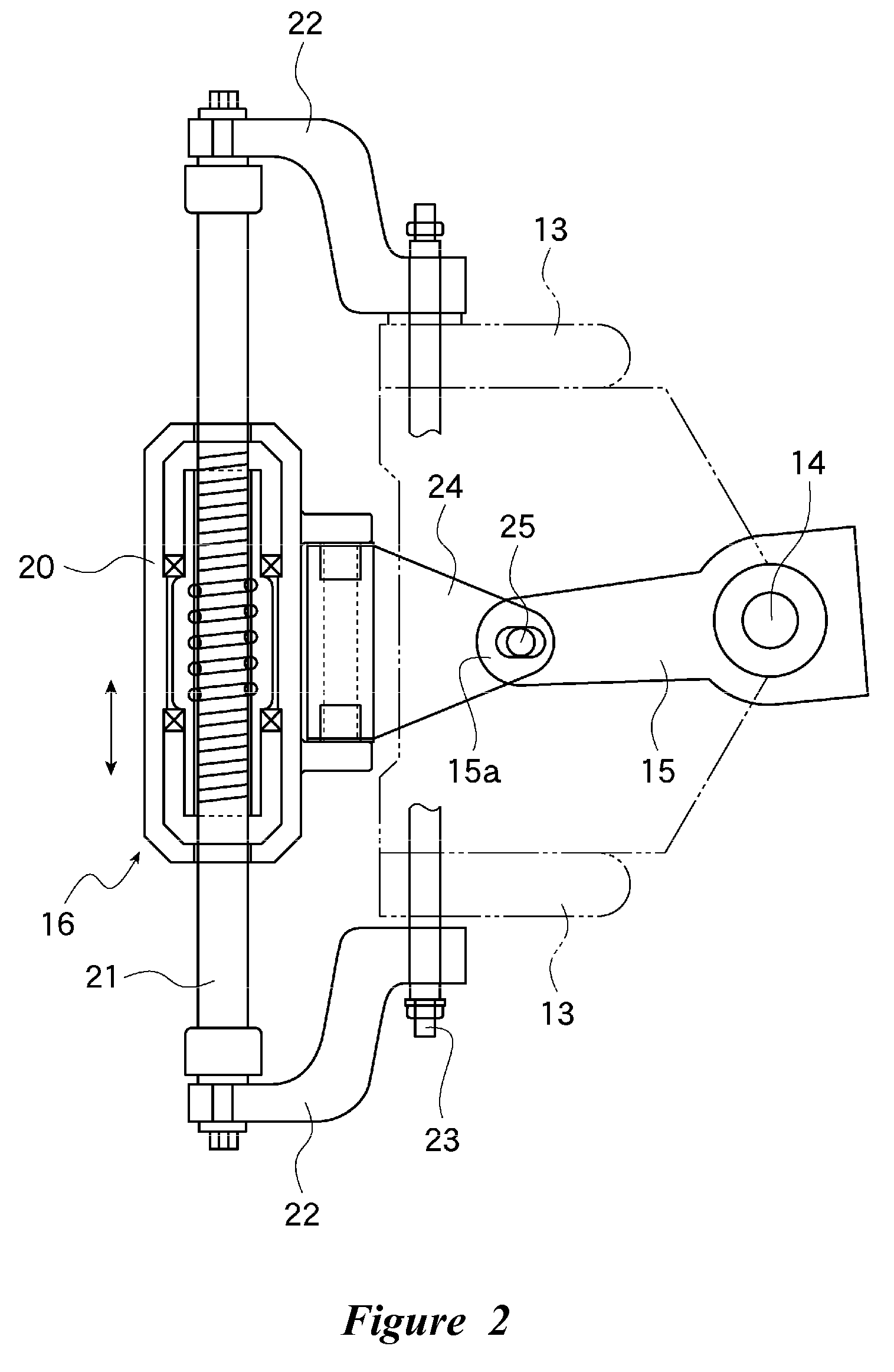
[0024]As shown in FIG. 1, a watercraft in accordance with this embodiment can have a hull 10 including a transom 11. To the transom 11, an outboard motor 12, which can serve as a “watercraft propulsion unit”, can be...


PUM


Abstract

A steering wheel, operable by an operator, can be electrically connected to an electric motor to provide an actuation signal corresponding to the amount of a steering wheel operation to the electric motor, a reaction motor for applying a reaction to the steering wheel, and an ECU for controlling the electric motor are provided. The ECU can include at least one of an operation status detection device for detecting an operation status corresponding to the steering wheel operation, a running status detection device for detecting a running status of the watercraft, an outboard motor status recognition device for recognizing a status of the outboard motor, such as the installation number thereof, and an electric motor status detection device for detecting a status of the electric motor. The ECU can also include a torque computation device for making a torque target value larger depending on the detection value from the at least one device, and a reaction motor control device for controlling the reaction motor in accordance with the torque target value computed by the torque computation device.

Description

PRIORITY INFORMATION[0001]The present application is based on and claims priority under 35 U.S.C. § 119 to Japanese Patent Application No. 2006-312161, filed on Nov. 17, 2006, the entire contents of which are expressly incorporated by reference herein.BACKGROUND OF THE INVENTIONS[0002]1. Field of the Inventions[0003]The present inventions relate to watercraft steering systems, and more particularly, to such systems having an electric actuator which is actuated as an operator turns a steering member and reaction force devices.[0004]2. Description of the Related Art[0005]Japanese Patent Document JP-A-2005-254848 discloses a steering system in which an electric actuator of the steering device is actuated as an operator operates the steering wheel. The watercraft is thus steered in response to the operation amount of the steering wheel.[0006]External forces on the watercraft are also is detected. Based on the detected external forces, a reaction torque is applied to the steering wheel. ...

Claims


Application Information

Patent Timeline
Patent Type & Authority Applications(United States)
IPC IPC(8): B63H25/00
CPCB63H20/12B63H25/42B63H25/24B63H25/02
Inventor MIZUTANI, MAKOTO
Owner YAMAHA MOTOR CO LTD
Learn More