
Method for Determining a Parameter Characteristic of the Fatigue State of a Part

a technology of fatigue state and parameter characteristic, which is applied in the direction of instruments, nuclear elements, digital computer details, etc., can solve the problems of successive deterioration or detrimental effect on material properties, limited lifetime or future usability of parts, and thermal stresses in parts and thus to direct load on parts

Inactive Publication Date: 2008-05-08
SIEMENS AG
View PDF16 Cites 6 Cited by
  • Summary
  • Abstract
  • Description
  • Claims
  • Application Information

AI Technical Summary

Benefits of technology

"The invention provides a method for predicting the fatigue state of a part or component by monitoring the load cycles it is subjected to over time. By taking into account the phases of the load cycle that have not yet been run, the method allows for a timely determination of the current fatigue state without having to wait for the completion of the entire load cycle. This enables better diagnosis and maintenance of the part, and reduces the likelihood of failure. The method can be used especially for components or parts that are subjected to a comparatively extended load cycle."

Problems solved by technology

These types of temperature difference can lead to thermal stresses in the part and thus to a direct load on the part.
The result of these types of time-varying loads is thus what is usually known as material fatigue or exhaustion of the part concerned, which is accompanied by a successive deterioration or detrimental effect on the material properties such as hardness or load capacity for example.
As the fatigue state of the part or the associated detrimental effect on its material properties increase, the part concerned may possibly no longer meet the specific design criteria such as load capacity or similar for example, so that as a result of the ongoing fatigue of the component concerned with time-varying loading, its lifetime or future usability are restricted.
The disadvantage of the concept described is however that the measured values included for the determination of the characteristic parameter for the exhaustion state, particularly with stress cycles, which, depending on the use of the relevant part, can only be computed over s significant period of for example months or even years, can only be made available in a timely manner under some conditions.

Method used


Image

  • Method for Determining a Parameter Characteristic of the Fatigue State of a Part
  • Method for Determining a Parameter Characteristic of the Fatigue State of a Part

Examples


Embodiment Construction

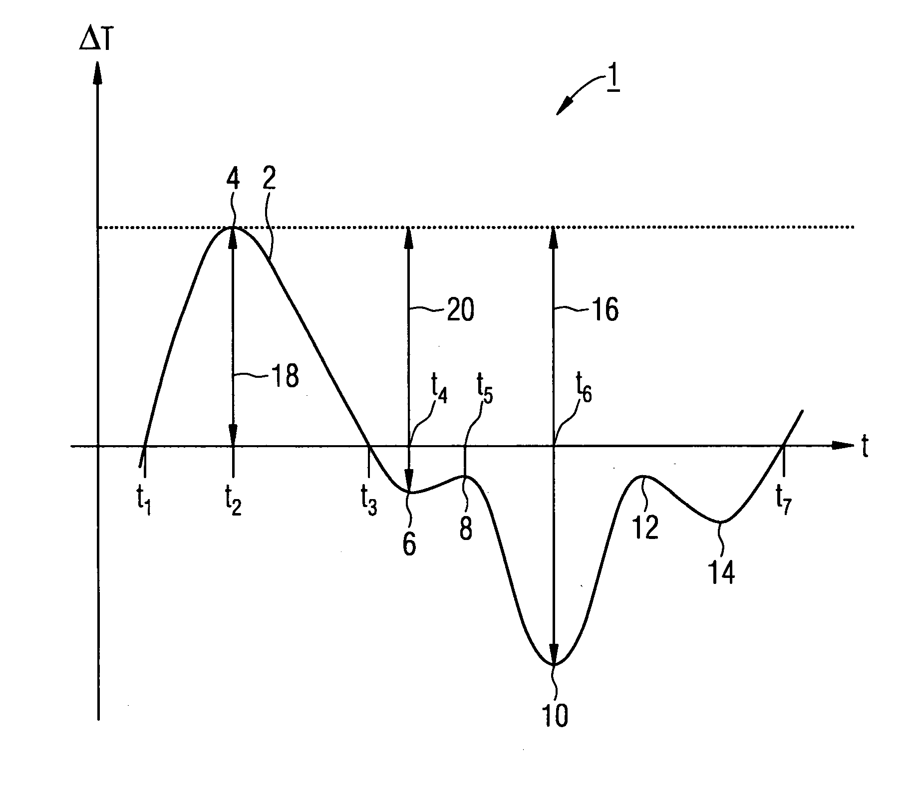
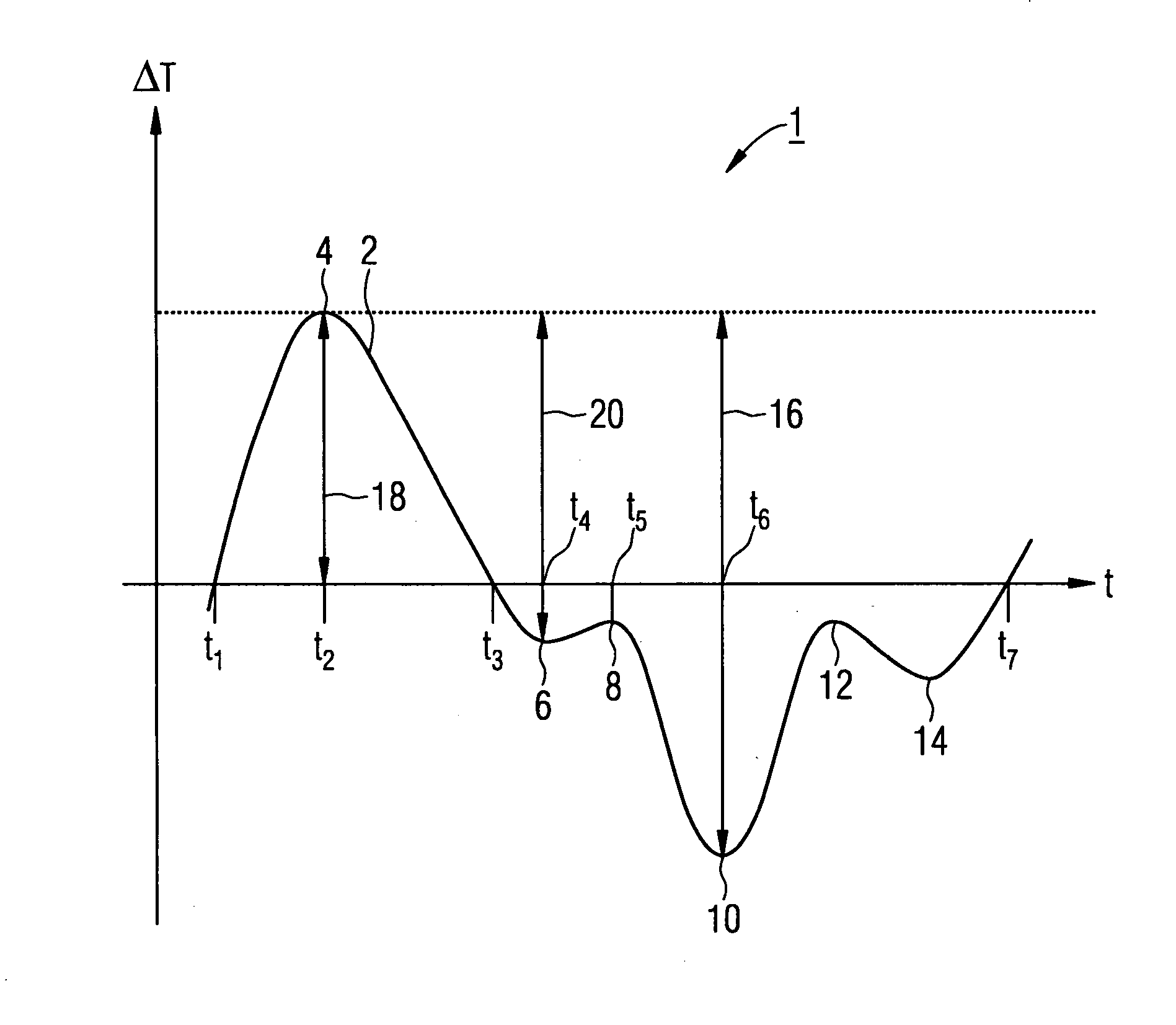
[0018]In the normal operating mode of a steam turbine, in a start or start-up phase, starting from the stationary turbine, there is a successively increasing application of a working medium at high temperature, which leads to the heating up especially of the components in contact with the medium. The heating up of the components directly exposed to the medium, such as the turbine blades for example or other parts directly exposed to medium, occurs in this case initially by a comparatively rapid warming up of the surfaces directly exposed to the medium, which as a result of the thermal inertia, depending on material and construction of the relevant component, especially of the relevant wall strength, propagates more quickly or less quickly into the internal area of the component concerned. In a transitional phase while the steam turbine is starting up, this means that, in a few components, there is a temperature difference between the outer side or surface on the one hand and the int...


PUM


Abstract

A method for determining an approximate value for a parameter characteristic of the fatigue state of a component as a result of a time-varying stress to which it is subjected by means of a number of load cycles should, itself, during comparatively lengthy stress cycles, enable a prognosis concerning the current fatigue state of the component, this prognosis being, in particular, adapted to the needs and suited for the real-time determination of maintenance intervals. To this end, in addition to optionally already fully completed load cycles, a first partially completed load cycle is also taken into consideration during the determination of the parameter, whereby temporary stress values for phases that have not yet been run through of the partially completed load cycle are, together with a predetermined fixed value, taken into consideration.

Description

CROSS REFERENCE TO RELATED APPLICATIONS[0001]This application is the US National Stage of International Application No. PCT / EP2005 / 055557, filed Oct. 26, 2005 and claims the benefit thereof. The International Application claims the benefits of European application No. 04025821.2 EP filed Oct. 29, 2004, both of the applications are incorporated by reference herein in their entirety.FIELD OF INVENTION[0002]The invention relates to a method for determining an approximate value for a parameter characteristic of the fatigue state of a part. The fatigue state of the part is based upon time-varying stress by means of a number of load cycles.BACKGROUND OF INVENTION[0003]In a plurality of applications in technical systems parts or components can be subjected to stresses which alternate or vary over time, of a mechanical or thermal nature for example. In such cases individual parts can for example be subjected to direct mechanical stresses through the occurrence of compression or tensile forc...

Claims


Application Information

Patent Timeline
Patent Type & Authority Applications(United States)
IPC IPC(8): F01D21/00G06F19/00
CPCF01D21/00F02C9/00G01N2203/0244G01N2203/0224G01N2203/0073
Inventor BODE, ANDREASGOBRECHT, EDWIN
Owner SIEMENS AG
Learn More