
Flow control systems and control valves therefor

a flow control and control system technology, applied in the field of fluid systems, can solve the problems of inability to achieve precise flow control, high shear, and high friction, and achieve the effects of enhancing control stability, minimizing pinch pressure, and reducing friction

Inactive Publication Date: 2008-05-08
INSIGHT PROCESS SOLUTIONS
View PDF4 Cites 11 Cited by
  • Summary
  • Abstract
  • Description
  • Claims
  • Application Information

AI Technical Summary

Benefits of technology

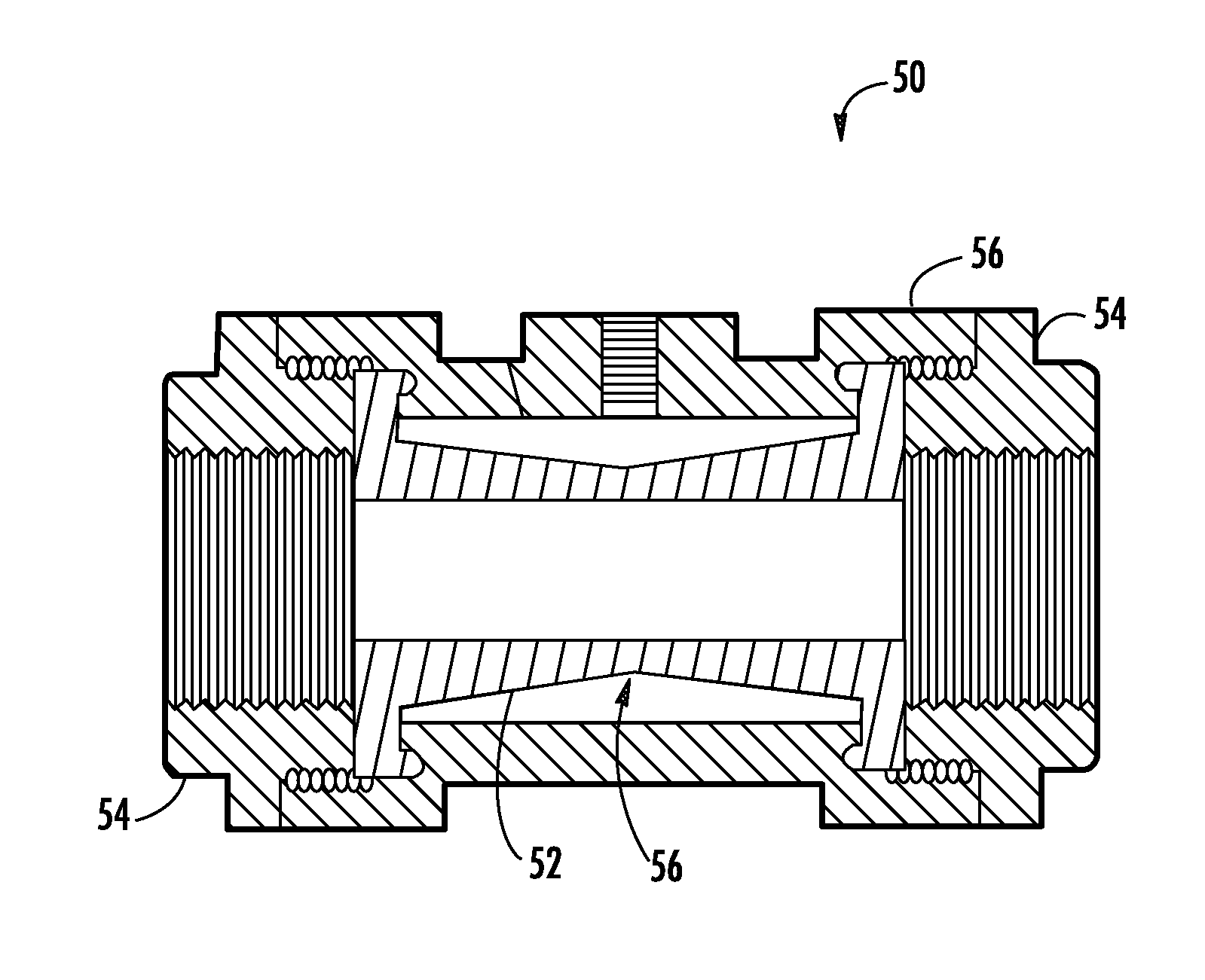
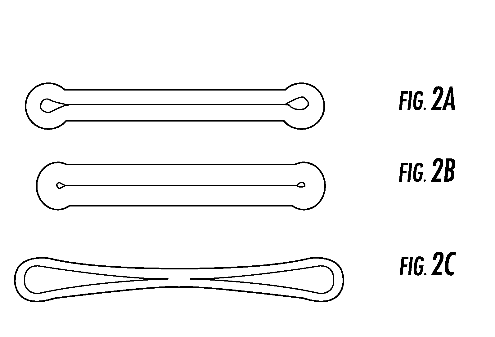
[0013] These and other shortcomings of the prior art are addressed by the present invention, which provides a control valve and a method for its use. The control valve has an elastomeric tube that is elongated relative to its inner diameter and correspondingly elongated in comparison with the elastomeric tubes of conventional air pinch valves. The elongated elastomeric tube, when constricted by applied pinch pressure, provides an internal passage whereby the pressure drop necessary to effect flow rate control is smoothly and gradually distributed along the conduit's elongated length. A method for using the control valve includes a sizing of the elastomeric tube such that a substantially larger cross section is employed than would be specified with conventional tubing system design. The method further includes providing an effective control logic for operating the control valve. The method further includes minimizing the pinch pressure required for control and thereby enhancing control stability via appropriate design of the entire flow system. The control valve precisely and stably controls flow rate over an extremely large dynamic range, and is highly suitable for low flow rates below 5 ml / min down to and below 0.1 ml / min. It also exhibits many other advantages over conventional control valves. The control valve can also be used to control an injection process.

Problems solved by technology

While a PD pump has the advantage of not requiring a flow meter, there are also many potential disadvantages, such as persistent pulsation, rotating seals that can leak, zones of high shear, viscosity dependency, flow rate drift, and mechanical complexity.
Because of limitations in the seat and stem geometry, precise flow control cannot be achieved when the stem seal nearly closes the seat, which occurs below about 10% of full flow range.
Furthermore, the moving stem and stem seal have friction which make it difficult for typical control valves to resolve flow rates less than 1% of full flow range.
Often, a valve which is controlled by an air signal requires a complex and expensive “positioner” to minimize the position hysteresis caused by valve friction.
In other words, these conventional valves cannot effectively control flow rates below 10% of full flow range and even in the controllable range, they cannot resolve the flow to better than about 1% of full flow range.
Further, valves of this construction are typically not available or sized for flow rates below 10 ml / min.
However, this intense shear is problematic for many industrially-important shear-vulnerable liquids such as latex suspensions and biological fluids which contain cells or dispersions or emulsions which may be damaged by local regions of high shear.
Moreover, the high velocity at the valve seat corresponds with low pressure similar to that occurring in the vena contracta of a venturi flow and this low pressure can result in liquid cavitation in certain cases.
Such cavitation can lead to bubble defects in certain applications, such as medical devices or coating systems.
Additionally, conventional control valves have stem seals that often seal along a sliding surface, allowing for the possibility of liquid leaks.
Finally, typical control valves have complex internal geometries which present numerous crevices which are difficult to clean and flush and can thereby result in cross contamination and the retention of unwanted bubbles.
Consequently, pinch valves can be utilized with liquids containing particulates such as abrasives and also corrosives, both of which are potentially problematic with conventional control valves having stems, stem seals and seats as described previously.
However, similar to the conventional control valve with a stem and seat, the resolution and hysteresis performance of these valves is limited by the friction in the mechanism, and the dynamic flow range for good control is limited by the mechanics of the pinching device and the geometry of the pinched elastomeric conduit.
This results in large changes of the flow caused by very small changes in applied pinch pressure.
Steady state injection systems suffer from difficulty in controlling the interface between the reactive components, especially as the flow rate of the minor injectant is reduced and / or intermittently stopped.
Any reduction in the velocity of the minor injectants can result in hardened or gelled build-up on the equipment at the interface of the fluids.
Conventional valve and tee designs do not provide a satisfactory interface, as any dead space (especially with an aspect ratio greater than 1 L / D, where L is the length of the dead space and D is the internal diameter) between the sealing point and the open stream of the major fluid can result in build-up.
Spring loaded check-type interface injector valves are sometimes used to control the interface, but are notorious for becoming plugged or stuck open.
The failure mechanism is that initially minute leakage through a conventional seal results in additional hardened material in the seal zone, contributing to a rapid failure.
However, if the actuated valve remains open during any period of very low or zero flow, the valve and upstream conduits are often contaminated with hardened materials.
The actuated valve design also fails to present high velocities (high shear rates, and high Reynolds numbers) of the injectant into the major component in order to effect thorough mixing.

Method used


Image

  • Flow control systems and control valves therefor
  • Flow control systems and control valves therefor
  • Flow control systems and control valves therefor

Examples


Embodiment Construction

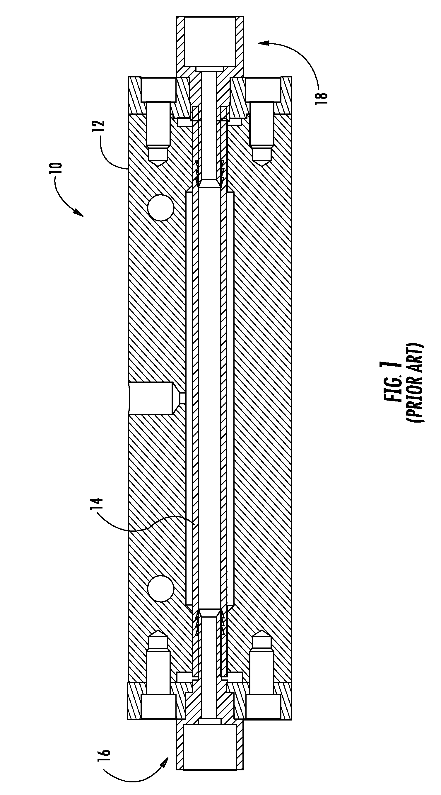
[0039] Referring to the drawings wherein identical reference numerals denote the same elements throughout the various views, FIG. 4 illustrates an exemplary control valve 100 constructed in accordance with an aspect of the present invention. The control valve 100 is similar to the prior art control valve 10 and has a rigid, generally cylindrical housing 112 with an inlet 116 and an outlet 118. An elastomeric tube 114 passing through the housing 112 has a flow passage 120 extending therethrough. The outer surface 122 of the tube 114 and the interior of the housing 112 cooperatively define a pressure chamber 124. A pressure port 126 in the sidewall of the housing 112 is in fluid communication with the pressure chamber 124.

[0040] A counterbore 128 is formed at each end of the housing 112. A cylindrical collar 130 is received in each counterbore 128 and surrounds the tube 114. The collars 130 are sealed to the housing 112 with O-rings 132 or other suitable seals. A fitting 134 with a b...


PUM


Abstract

A fluid system, a control valve therefor, and a method of its operation are provided. The fluid system includes a piping run, and a control valve which includes: a housing having an inlet connected to the piping run, an outlet connected to the piping run, and a pressure port; and a elastomeric tube disposed inside the housing, the tube having a flow passage extending therethrough which is in fluid communication with the inlet and outlet. An outer surface of the tube and the housing cooperatively define a pressure chamber which is in fluid communication solely with the pressure port, A source of controlled fluid pressure is connected to the pressure port to modulate flow in the tube. The tube is sized and the valve is operated so as to provide accurate flow rate control.

Description

CROSS-REFERENCE TO RELATED APPLICATIONS [0001] This application claims the benefit of Provisional Application No. 60 / 828,657, filed Oct. 8, 2006.BACKGROUND OF THE INVENTION [0002] This invention relates generally to fluid systems, and more particularly to flow control valves and methods of operation. [0003] Accurate flow rate control is required in order to successfully achieve many commercially important processes involving liquid transport. For example, accurate, steady delivery flow rate is required in precision pre-metered coating processes. Flow rate control is typically achieved with a form of positive displacement (“PD”) pump or a metering valve. While a PD pump has the advantage of not requiring a flow meter, there are also many potential disadvantages, such as persistent pulsation, rotating seals that can leak, zones of high shear, viscosity dependency, flow rate drift, and mechanical complexity. [0004] Flow rate control achieved via the action of a control valve operated w...

Claims


Application Information

Patent Timeline
Patent Type & Authority Applications(United States)
IPC IPC(8): F16K31/12F16K27/00B67D7/08
CPCF16K7/07Y10T137/0318
Inventor JENNINGS, JEFFREY D.KELLAR, FRANZ W.
Owner INSIGHT PROCESS SOLUTIONS
Learn More