Switch

a technology of swivel and swivel, which is applied in the field of swivel, can solve the problems of short lifetime and difficult fatigue to prolong the lifetime, and achieve the effect of smooth operation and easy swivel

Inactive Publication Date: 2008-05-01
ORMON CORP
View PDF4 Cites 8 Cited by
  • Summary
  • Abstract
  • Description
  • Claims
  • Application Information

AI Technical Summary

Benefits of technology

[0005]However, as is clear from FIGS. 2 and 6 of Japanese Patent Application Laid-Open No. 2004-362979, in the switch, because a turning shaft center of the turning handle body 2 is matched with a turning shaft center of the returning spring member 3, a turning angle of the turning handle body 2 is always equal to an opening angle between end portions 3a and 3b of the returning spring member 3. As a result, when an operating angle of the turning handle body 2 is increased to facilitate the operation, the opening angle of the end portions 3a and 3b of the returning spring member 3 is increased to require a large operating force. Additionally, a load applied to the returning spring member 3 is increased and fatigue is easy to occur, which results in a problem of a short lifetime.
[0006]In view of the foregoing, an object of the present invention is to provide a long-life switch which can be operated by a small operating force.
[0008]According to the aspect of the present invention, the turning shaft center of the swingably supported coil spring is disposed eccentrically to the operation lever. When the operation lever is turned to turn the arm portion of the coil spring, the coil portion of the coil spring is swung, and an opening angle of the arm portion in the coil spring is smaller than a turning angle of the operation lever. Therefore, because the spring force of the coil spring is not directly proportional to the turning angle of the operation lever, the operation lever can be operated with smaller operating force. Additionally, because the arm portion of the coil spring has the smaller opening angle, the small load is applied to the coil spring. Therefore, the fatigue is difficult to occur to lengthen the lifetime.
[0011]The bending moment to the arm portion based on the operating rib projected from the operation lever is larger than the bending moment to the arm portion latched in the base. Therefore, the coil spring is easily swung, and smooth operating feeling is obtained.

Problems solved by technology

Additionally, a load applied to the returning spring member 3 is increased and fatigue is easy to occur, which results in a problem of a short lifetime.
Therefore, the fatigue is difficult to occur to lengthen the lifetime.

Method used


Image

  • Switch
  • Switch
  • Switch

Examples


Embodiment Construction

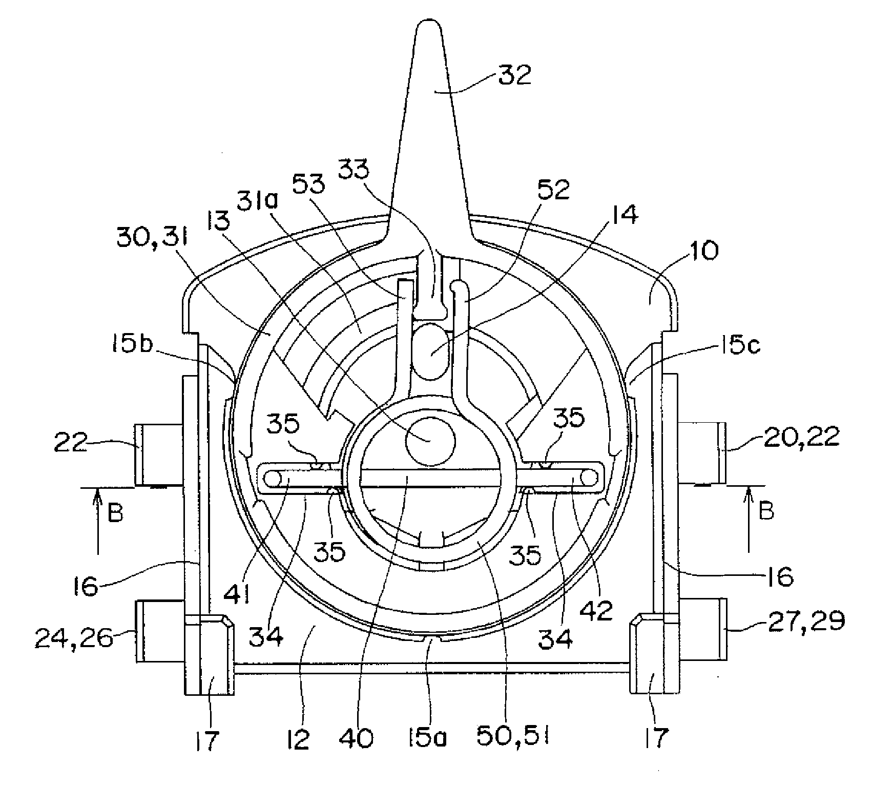
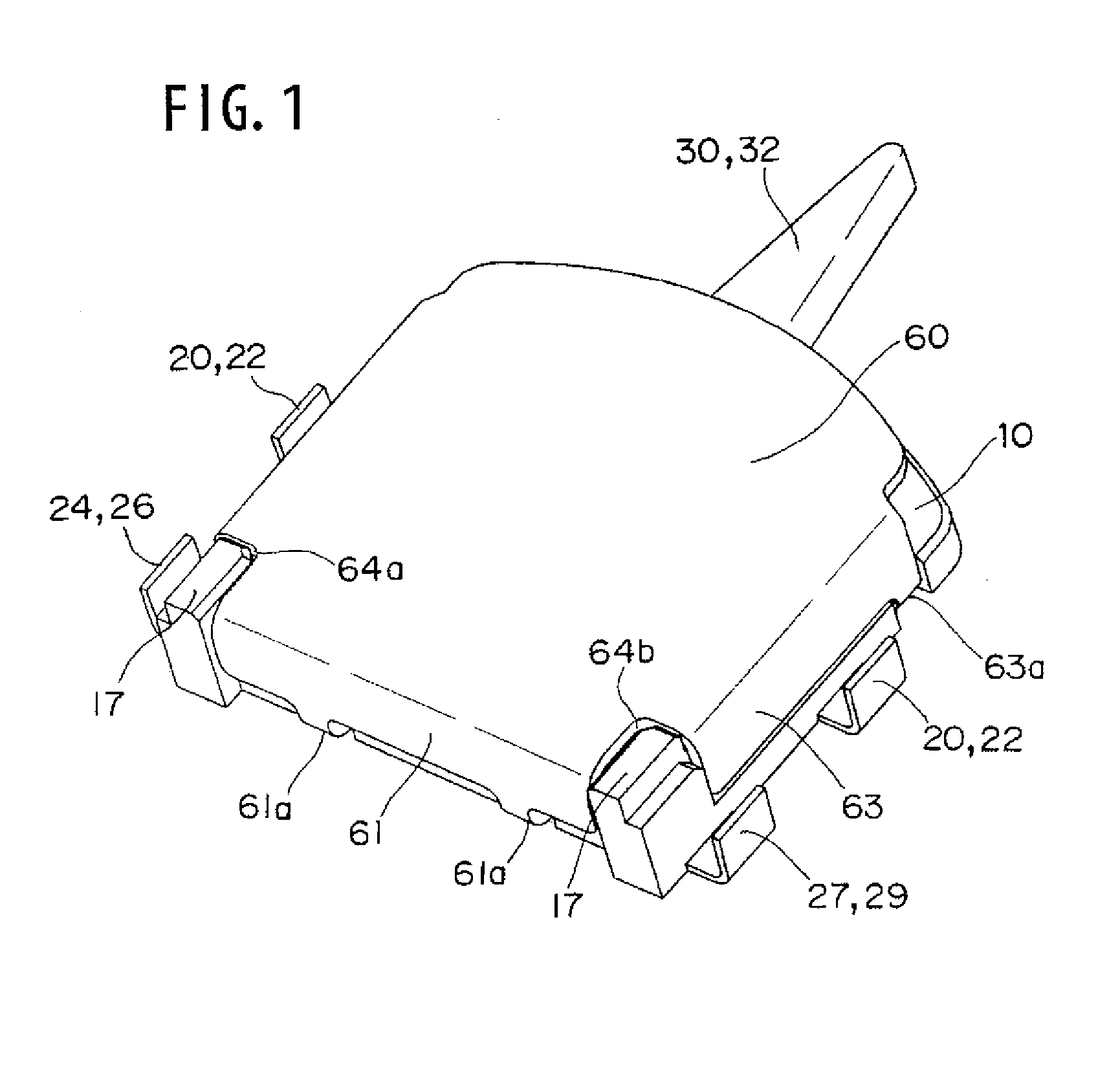
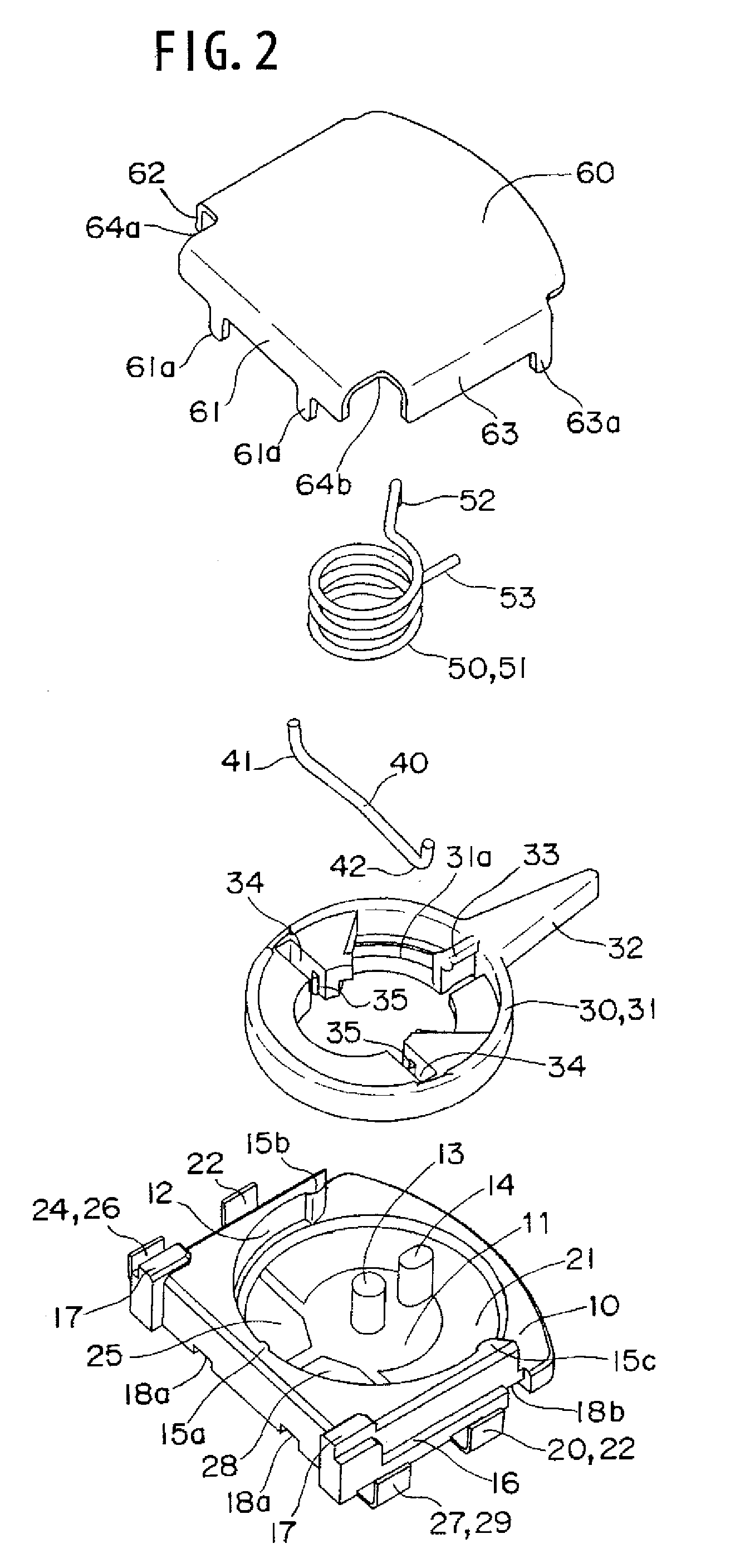
[0023]Preferred embodiments of the present invention will be described with reference to the accompanying drawings of FIGS. 1 to 11. As shown in FIGS. 1 to 8, a first embodiment is based on application to a compact switch surface-mounted on a printed board. As shown in FIG. 2, the switch includes a base 10, an operation lever 30, a movable contact piece 40, a coil spring 50, and a cover 60. The base 10 has a substantially square shape in plan view, and a common fixed contact terminal 20 and a pair of switching fixed contact terminals 24 and 27 are insert-molded in a bottom surface of the base 10. The operation lever 30 is turnably supported along an upper surface of the base 10. The movable contact piece 40 is formed by a bent rod-shape conductive spring member, and the movable contact piece 40 is fitted in fitting grooves 34 of the operation lever 30. The coil spring 50 presses the movable contact piece 40 to impart a contact pressure. The base 10 is covered with the cover 60, and ...


PUM


Abstract

A long-life switch includes a base in which fixed contact portions are exposed in a concentric manner in an upper surface thereof; an operation lever whose turning shaft center is disposed on a shaft center of a lever portion, and turnably supported along the upper surface of the base; a movable contact piece in which movable contact portions disposed at both ends of the movable contact piece are slidably disposed to the fixed contact portions; and a coil spring in which a shaft center of a coil portion is disposed eccentrically to a turning shaft center of the operation lever, the coil spring latching an arm portion extended from one end side of the coil portion to the upper surface of the base while swingably supporting the coil portion, the coil spring latching an arm portion extended from the other end side of the coil portion to the operation lever.

Description

BACKGROUND OF THE INVENTION[0001]1. Field of the Invention[0002]The present invention relates to a switch, particularly to a switch which is surface-mounted on a printed board.[0003]2. Description of the Related Art[0004]Conventionally, as for the switch surface-mounted on the printed board, there is proposed a switch wherein a returning spring member 3 is twisted to impart a returning force to a turning handle body 2 by turning the turning handle body 2 and an irregular shaped movable contact spring 4 formed by pressing of an elastic metal thin plate is rotated to open and close a contact (refer to, for example, Japanese Patent Application Laid-Open No. 2004-362979).SUMMARY OF THE INVENTION[0005]However, as is clear from FIGS. 2 and 6 of Japanese Patent Application Laid-Open No. 2004-362979, in the switch, because a turning shaft center of the turning handle body 2 is matched with a turning shaft center of the returning spring member 3, a turning angle of the turning handle body 2 ...

Claims


Application Information

Patent Timeline
IPC IPC(8): H01H21/24
CPCH01H1/365H01H21/24H01H1/44H01H1/403
Inventor KIYONO, YASUHIRONARUO, TOSHIHIRO
Owner ORMON CORP
Why Eureka
Try Eureka