
Roller body for roller bearing

A technology of rolling bearings and rolling elements, applied in the field of rolling elements, can solve the problems of material and cost consumption, consumption, etc.

Active Publication Date: 2012-04-11
AB SKF
View PDF5 Cites 17 Cited by
  • Summary
  • Abstract
  • Description
  • Claims
  • Application Information

AI Technical Summary

Problems solved by technology

However, this results in greater material and cost expenditure
In addition, rolling bearings may be subject to regular inspections, which also means higher costs

Method used


Image

  • Roller body for roller bearing
  • Roller body for roller bearing
  • Roller body for roller bearing

Examples


Embodiment Construction

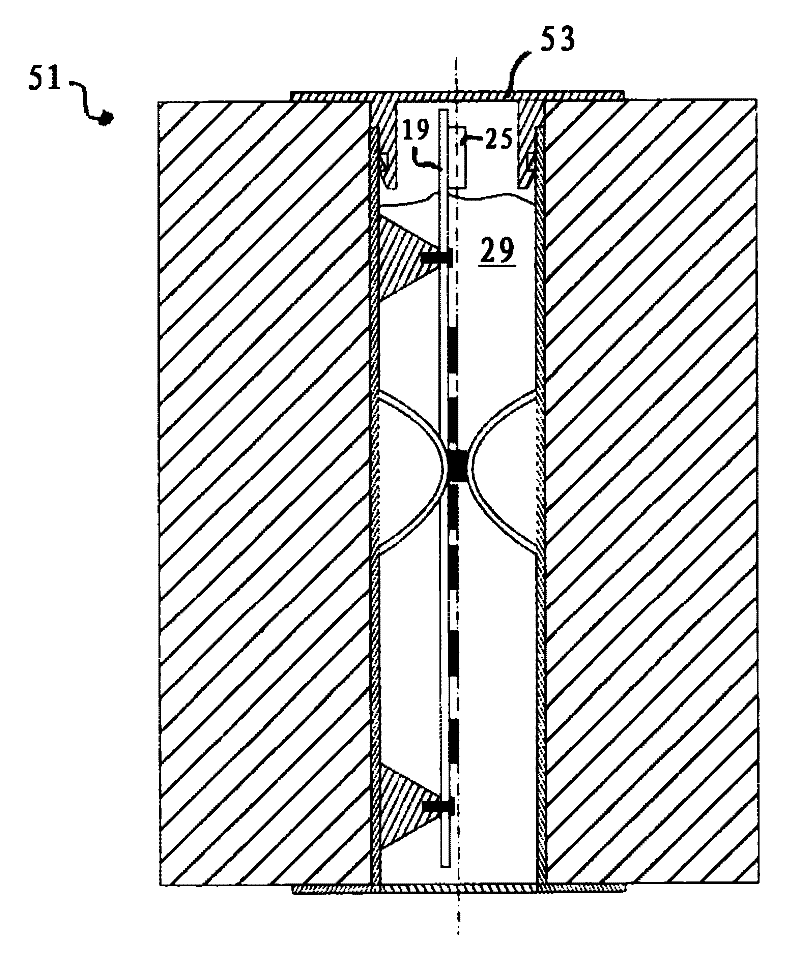
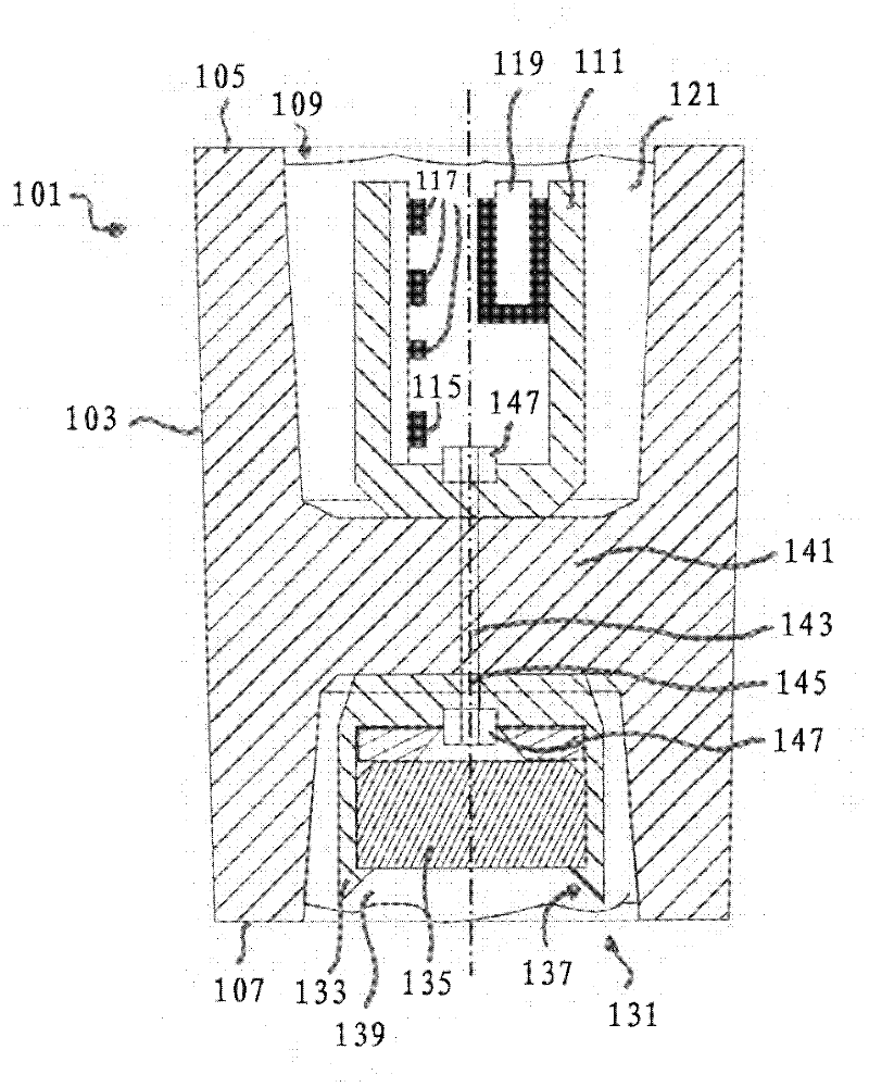
[0029] The embodiments described below relate by way of example to cylindrical or tapered rollers. Correspondingly, however, other types of rollers, such as spherical rollers, cylindrical and tapered rollers, can also be configured accordingly. exist figure 1 In , a cylindrical roller 1 is shown as an embodiment of the present invention. The cylindrical roller 1 has a radially surrounding running surface 3 , by means of which the cylindrical roller 1 can make rolling contact with an inner ring or an outer ring (not shown here) of the rolling bearing. Furthermore, the cylindrical roller 1 has two end sides 5 and 7 that essentially have a round basic shape. A bore 9 arranged centrally in the cylindrical roller 1 extends between the end sides 5 and 7 . A support 11 is arranged in the bore 9 , which likewise has a hollow cylindrical basic shape. The outer diameter of the bracket 11 is adapted to the inner diameter of the hole 9 .

[0030] In order to securely fix the carrier ...


PUM


Abstract

A roller body for a roller bearing includes at least one cavity extending from an end face of the roller body, at least one retaining element is disposed in the cavity, and at least one sensor is disposed in the cavity, such as in or on the retaining element. The sensor is at least partially surrounded by an elastic material in a protective manner.

Description

technical field [0001] The invention relates to a rolling element for a rolling bearing. Background technique [0002] In the use of rolling bearings, the generally rotational movement between two bearing rings can be achieved by the rolling movement of the rolling bodies arranged between them. To accommodate relatively high loads, for example in wind power installations or in the automotive and heavy machinery industries, cylindrical roller bearings or tapered roller bearings are preferably used. In cylindrical roller bearings, the rolling elements have a cylindrical basic shape, in tapered roller bearings, the rolling elements have a conical basic shape. In particular large radial loads can be transmitted via cylindrical roller bearings, whereas tapered roller bearings can only additionally accommodate axial loads. [0003] During operation, rolling bearings are generally subjected to numerous ambient influences which are detrimental to the running and service life chara...

Claims


Application Information

Patent Timeline
Patent Type & Authority Applications(China)
IPC IPC(8): F16C33/34F16C19/52
CPCF16C33/34F16C33/366F16C41/008F16C19/522
Inventor A.斯图本劳克A.奥尔彻维斯基A.德夫里斯S.齐格勒G.克里斯琴森E.西格尔F.德维特H.莫尔
Owner AB SKF
Learn More