Method and apparatus for producing combined optical film, combined optical film, image display, and methods for producing liquid crystal panel and laminated optical film

a combined optical film and laminate technology, applied in the direction of lamination, non-linear optics, domestic applications, etc., can solve the problems of light leakage, large space required, high cost, etc., and achieve the effect of convenient transportation and simple process

Inactive Publication Date: 2008-05-01
NITTO DENKO CORP
View PDF20 Cites 15 Cited by
  • Summary
  • Abstract
  • Description
  • Claims
  • Application Information

AI Technical Summary

Benefits of technology

[0044] The production method of the invention can be efficiently achieved with the production apparatus.
[0045] According to the invention, a combined optical film with a narrowed gap between opposed end faces can be manufactured by a simple process. The combined optical film is prepared with the plurality of optical films. Thus, optical films with the desi

Problems solved by technology

For the manufacture of large-area optical films, corresponding large manufacturing facilities are necessary, and a difficulty in handling for packing is associated with transportation, which requires high cost.
In order to install such large manufacturing facilities, a large place is required.
Thus, butting of the end faces of liquid crystal displays has a p

Method used


Image

  • Method and apparatus for producing combined optical film, combined optical film, image display, and methods for producing liquid crystal panel and laminated optical film
  • Method and apparatus for producing combined optical film, combined optical film, image display, and methods for producing liquid crystal panel and laminated optical film
  • Method and apparatus for producing combined optical film, combined optical film, image display, and methods for producing liquid crystal panel and laminated optical film

Examples


example 1

Optical Film

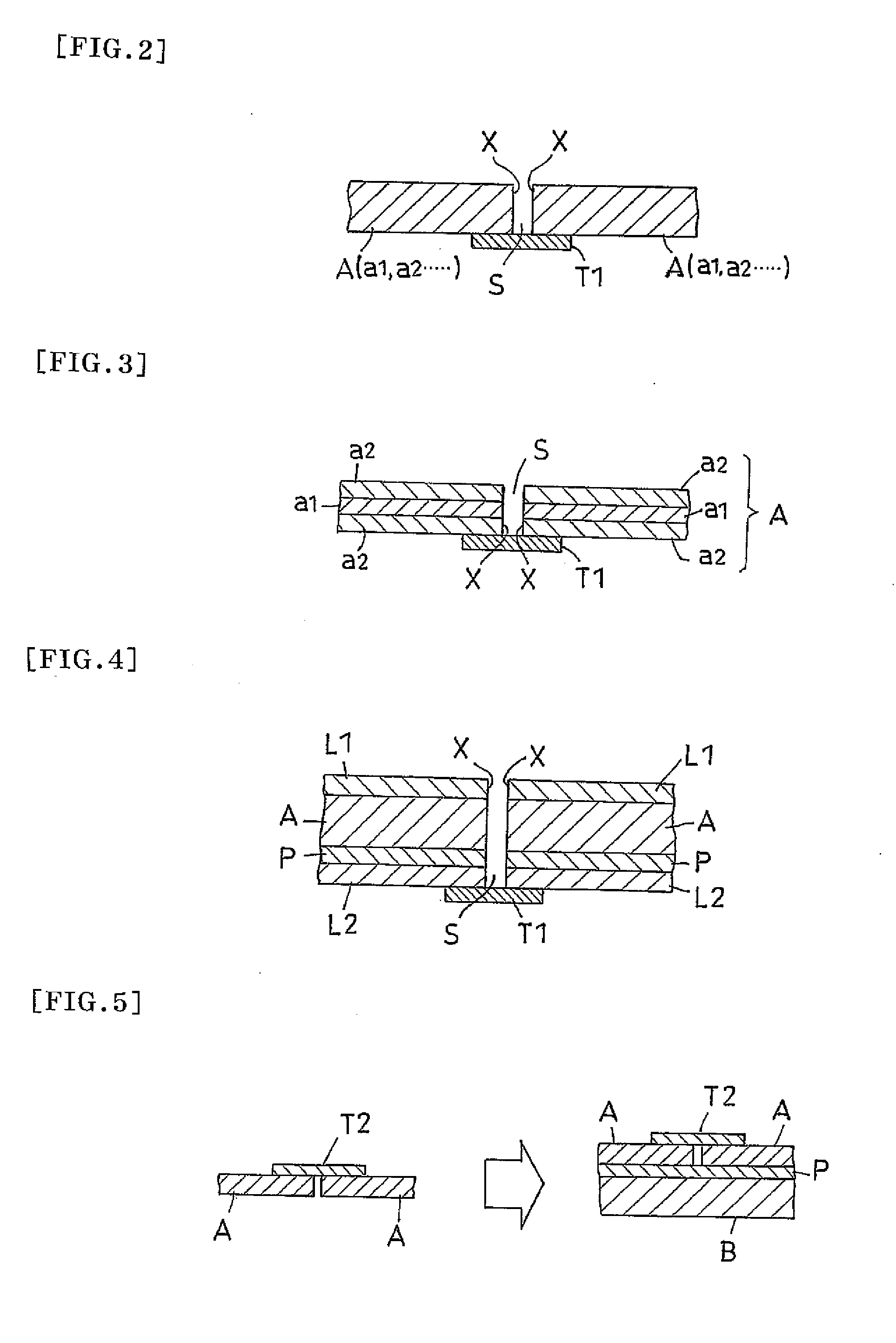
[0158] An optical film manufactured by Nitto Denko Corporation (NXP-EF / SEGK-ST03) was used. This film is a retardation layer-laminated polarizing plate including a polarizing plate and a retardation layer formed on one side of the polarizing plate, in which a separator, a pressure-sensitive adhesive layer, the polarizing plate, the retardation layer, and a protective film are laminated in this order.

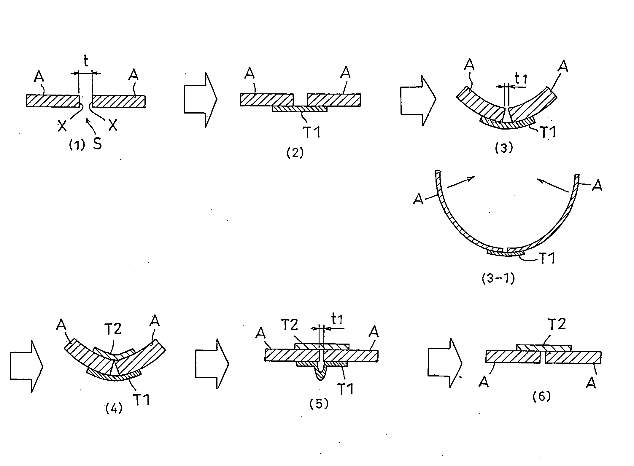
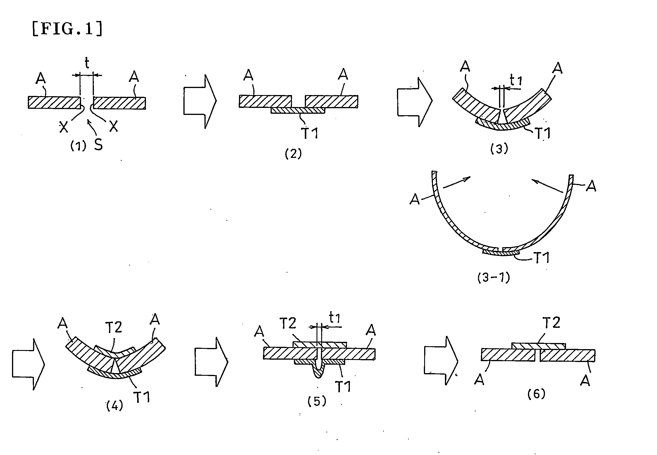
[0159] One of the end faces (length side) of the optical film (100 mm in length, 50 mm in width, 300 μm in thickness) was processed such that the processed end face was in the same direction as the normal direction of the optical film.

[0160] First and Second Seal Materials

[0161] The first and second seal materials used were each a polyimide tape manufactured by Nitto Denko Corporation (Polyimide Pressure-Sensitive Adhesive Table No. 360A) with a width of 10 mm and a thickness of 53 μm. The polyimide tape has a tensile elasticity of 1700 MPa.

[0162] Method for Producing Co...

example 2

[0169] A combined optical film was obtained using the process of Example 1, except that a light packing tape manufactured by Sekisui Chemical Co., Ltd. (Cellophane Tape No. 252, 10 mm in width and 51 μm in thickness) was used as both of the first and second seal materials. The cellophane tape has a tensile elasticity of 2300 MPa.

example 3

[0170] A combined optical film was obtained using the process of Example 1, except that the width t of the gap s between the opposed end faces was set at 43 μm in the step (1).


PUM

PropertyMeasurementUnit
Widthaaaaaaaaaa
Pressureaaaaaaaaaa
Flexibilityaaaaaaaaaa

Abstract

It is an object of the invention to provide a method for producing a combined optical film that includes opposing the end faces of a plurality of optical films to one another and can narrow the gap between the opposed end faces. A method for producing a combined optical film comprising a plurality of optical films each having at least one end face at which the optical films are opposed to one another, comprising the steps of: (1) opposing the end faces of the optical films to one another with a gap provided therebetween; (2) bonding a first seal material to the opposed portions of the optical films on a first side of each optical film to join the optical films; (3) bending the joined opposed portions of the optical films such that the joined opposed portions become concave on a second side of each optical film where the first seal material is not bonded and such that the gap is narrowed on the second side; (4) bonding a second seal material to the opposed portions on the second side, while the joined optical films are bent such that the gap is narrowed on the second side; and (5) cancelling the bending of the joined optical films to make them flat.

Description

BACKGROUND OF THE INVENTION [0001] (1) Field of the Invention [0002] The invention relates to a method for producing a combined optical film including a plurality of optical films with their end faces opposed to one another and to an apparatus for use in the production method. The invention also relates to a combined optical film obtained by the production method. The combined optical film obtained by the production method is suitable for use in methods of producing a liquid crystal panel and a laminated optical film. The invention also relates to an image display, such as a liquid crystal display and an organic electroluminescent display, using the combined optical film. [0003] Examples of the optical film include a polarizer, a protective film to be laminated on one or both sides of a polarizer, a polarizing plate including a polarizer and the protective film laminated on one or both sides of the polarizer, a retardation plate, an optical compensation film, and a brightness enhanc...

Claims


Application Information

Patent Timeline
IPC IPC(8): B32B37/00B29C53/80B29C63/00
CPCB29C65/5042Y10T156/1142B29C66/43B29K2001/00B29K2023/00B29K2023/12B29K2025/00B29K2029/00B29K2067/00B29K2069/00B29K2077/00B29K2079/08B29K2081/06B29K2101/12B29K2305/12B29K2995/0018B29K2995/0026B29K2995/0034B29K2995/0051B29L2009/00B29L2009/003B29L2011/00G02F1/133528B29C66/1142Y10T156/1933B29C65/5014B29C65/4845B29C65/4875B29C65/4865B29C65/4825B29C65/483Y10T156/19B29C65/00B29C66/71B29C66/723B29C66/7338B29K2067/003B29K2033/12B29K2029/04B29K2027/06B29K2025/06B29K2023/06G02F1/1335
Inventor YAMADA, TAKUYAMAMOTO, SATORU
Owner NITTO DENKO CORP
Why Eureka
Try Eureka