
Oscillation-Dampened Roller

a technology of oscillation dampening and roller, which is applied in the field of roller, can solve the problems of dampening the oscillations in the machine bed and therefore the entire machine, and achieve the effects of effective dampening oscillations and vibrations, and reducing the volume of the chamber

Inactive Publication Date: 2008-04-24
SHW CASTING TECH +1
View PDF10 Cites 0 Cited by
  • Summary
  • Abstract
  • Description
  • Claims
  • Application Information

AI Technical Summary

Benefits of technology

[0011]For machine tools, DE 100 46 868 C2 discloses filling the machine bed of a machine tool with a mixture having a pulpy consistency and consisting of a liquid and granular solids. This can effectively dampen oscillations which enter the machine bed during operation. The machine bed transfers the oscillations onto the liquid, which for its part tries to move the solid grains. Due to their mass inertia, however, the solid grains stay in place, and there is a relative movement between the liquid and the grains. Liquid friction on the grains and turbulence in the liquid itself dissipate energy, which dampens the oscillations in the machine bed and therefore the entire machine.
[0024]An additional positive effect is that a roller in accordance with the invention is also capable of effectively dampening oscillations and vibrations generated by other components with which the roller cooperates in treating the web, for example one or more companion rollers, by drives, bearings, etc. or also by the web-shaped medium itself. Thus, for example, a significant improvement can also be expected with regard to the occurrence of barring, as is a fear with calenders.
[0025]Lastly, even in the range of the so-called semi-critical speed, a roller in accordance with the invention also exhibits greater smooth running than a roller which is identical in design but has no filling. Semi-critical resonances occur when there is anisotropy in the roller cross-section. Such a roller then has different rigidities in two planes perpendicular to each other. If such a roller, mounted in its two trunnions and under its own weight or an additional linear load, is rotated once about its axis, the magnitude of its sagging passes through two periods. Such a roller experiences a stimulation twice at a rotational speed corresponding to half its resonant frequency, i.e. at this speed, it is stimulated at a frequency corresponding to its resonant frequency. Given this stimulation, the dampening by the filling becomes fully effective.
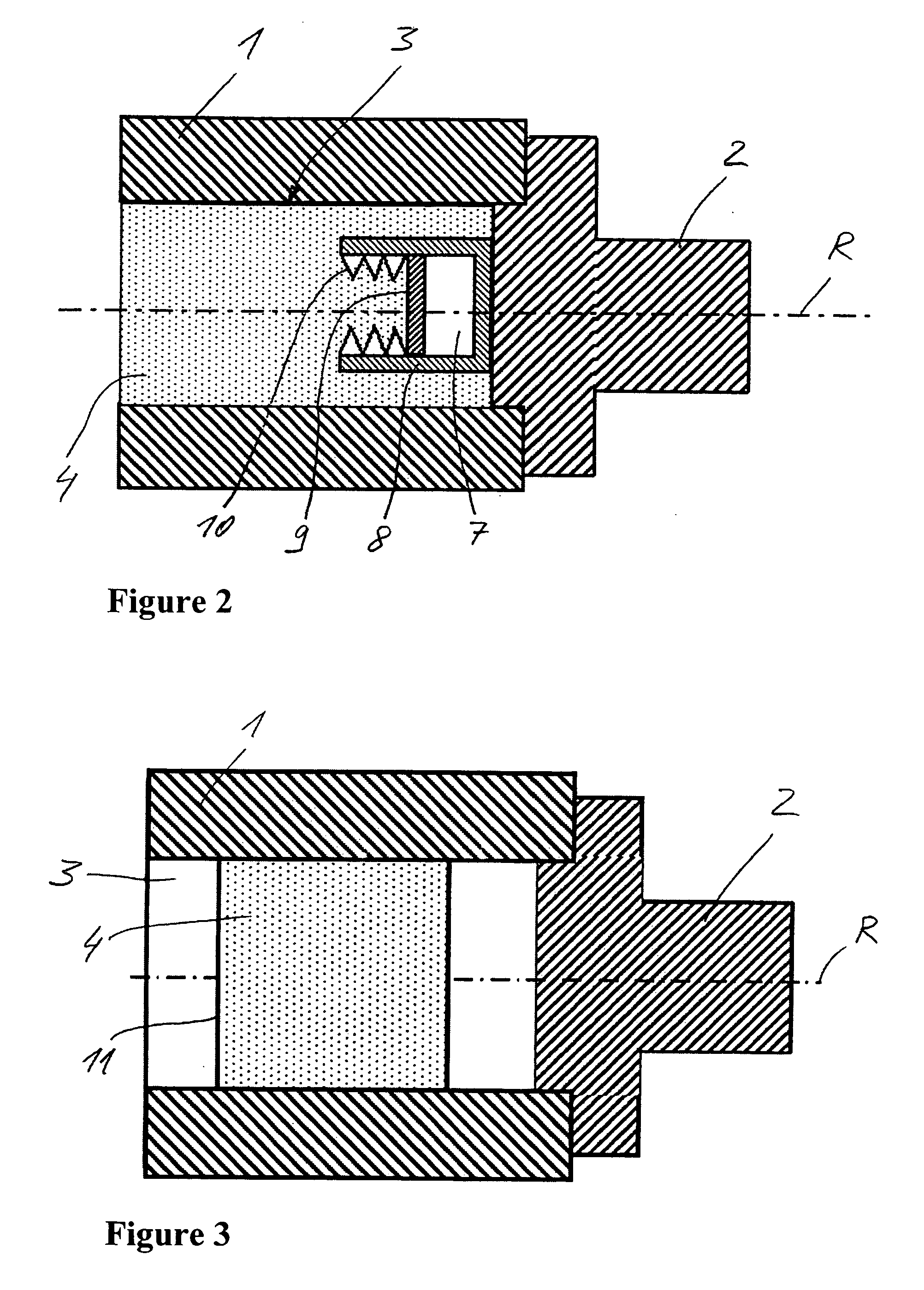
[0026]In preferred embodiments, the mixture can be charged with a pressure burden, preferably by means of a chamber which can be or is already expanded by a hydraulic fluid. The chamber is preferably arranged within the mixture, but can in principle also form an outer wall of a hollow space which in this case is as a whole variable in its volume. The walls of the chamber are flexible, as a whole or in areas. In the latter case, the chamber is formed by a bubble. The chamber can however also be formed only from rigid chamber walls, at least one of which can move with respect to at least one other container wall and so vary the enclosed volume. Such a chamber can in particular be formed in the manner of a piston-cylinder arrangement, wherein a chamber wall forming the piston is preferably linearly guided by the surrounding chamber wall. A combination of flexible and moving, rigid chamber walls is also advantageous. The chamber can in particular be formed by means of an elastic restoring means, in particular bellows, preferably metal bellows. The moving container wall cited can be fastened to a top end of the bellows or can be formed directly by the top end, while the bottom end of the bellows is connected to another container wall. The pressure force of the enclosed fluid and the elasticity force of the bellows advantageously superimpose each other positively, such that if the mixture expands in volume, the volume of the chamber is reduced and the chamber pressure and also the restoring elasticity force of the bellows are thus increased. The chamber can advantageously compensate for changes in the volume of the hollow space and / or the mixture situated in it and can thus act as an equalizing chamber. Changes in volume even occur solely due to changes in the temperature of the roller.

Problems solved by technology

Liquid friction on the grains and turbulence in the liquid itself dissipate energy, which dampens the oscillations in the machine bed and therefore the entire machine.

Method used


Image

  • Oscillation-Dampened Roller
  • Oscillation-Dampened Roller
  • Oscillation-Dampened Roller

Examples


Embodiment Construction

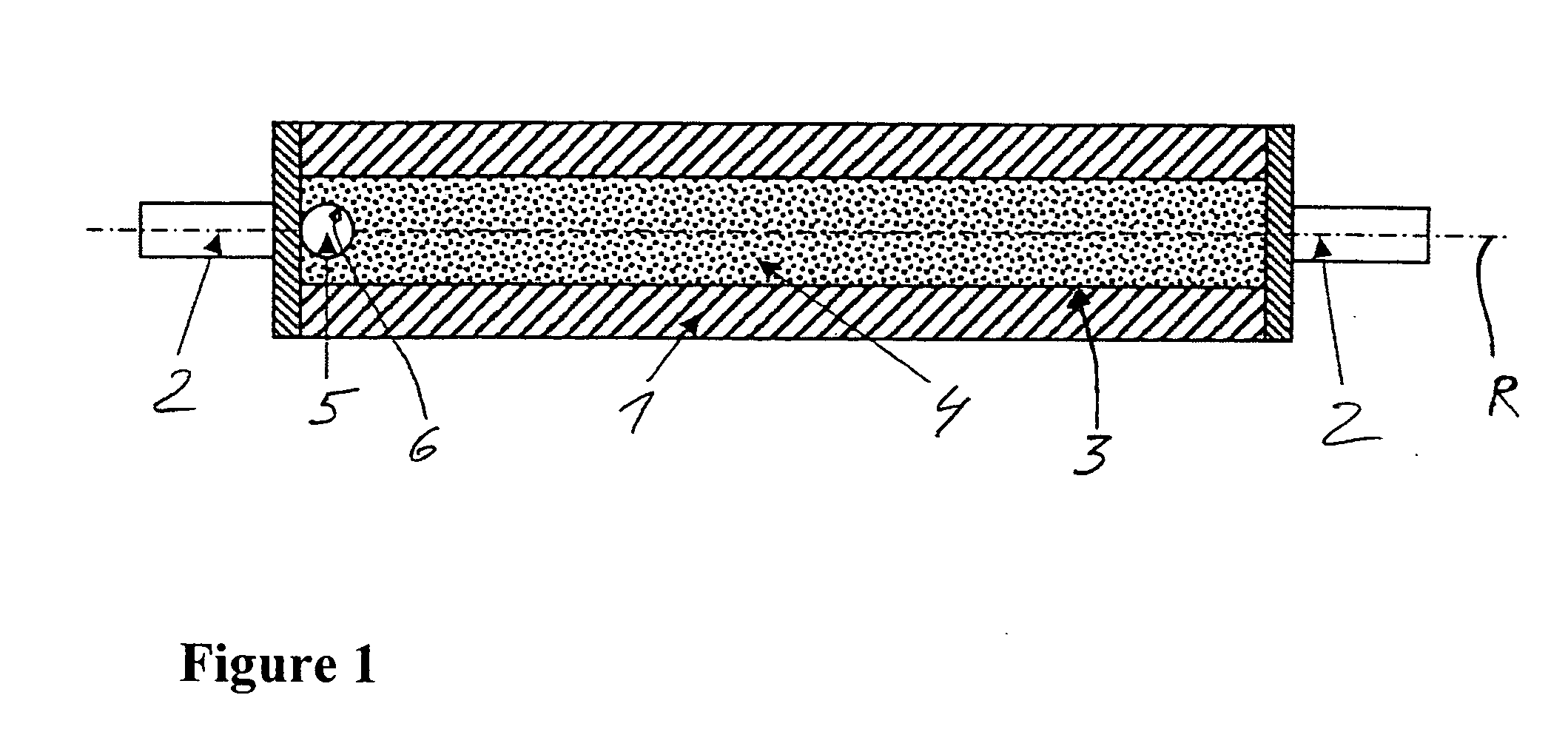
[0037]FIG. 1 shows a roller in a first example embodiment, comprising a circular cylindrical roller shell 1 to which a trunnion 2 is fastened via a trunnion flange at each of its two axial ends. The roller thus obtained can be mounted on its two trunnions 2 such that it can be rotated and driven about a rotational axis R. The roller can in particular be a calender roller for smoothing a paper web.

[0038]In the roller shell 1, which is rotationally symmetrical with respect to the rotational axis R, a central hollow space 3 is formed which is likewise rotationally symmetrical with respect to the rotational axis R. On its peripheral side, the shell inner surface of the roller shell 1 forms the wall of the hollow space. The two trunnion flanges seal the hollow space 3 at the two axial front sides of the roller shell 1.

[0039]The hollow space is filled with a mixture 4 consisting of a liquid and a multitude of solid particles. The solid particles are granular. The mixture 4 as a whole exhi...


PUM

PropertyMeasurementUnit
Pressureaaaaaaaaaa
Volumeaaaaaaaaaa
Flexibilityaaaaaaaaaa

Abstract

A web processing roll comprising at least one cavity. The cavity of the roll is at least partially filled with a mixture of a liquid and at least one mixing partner that is insoluble in the liquid. Solid particles, preferably a granular solid, or another liquid constitute the mixing partner.

Description

[0001]This application is the U.S. national phase application of PCT International Application No. PCT / EP2004 / 011298, filed Oct. 8, 2004, which claims priority to German Patent Application No. DE 103 58 292.4, filed Dec. 12, 2003.BACKGROUND OF THE INVENTION[0002]1. Technical Field[0003]The invention relates to a roller for a web-shaped medium, preferably for mechanically, thermally or thermo-mechanically treating a web-shaped medium.[0004]The treatment can in particular be pressing, drying or smoothing the medium, or a combination of these types of processing. The medium is preferably a paper web.[0005]2. Description of the Related Art[0006]Such rollers are for example used in calenders, with which paper webs are smoothed. Calenders comprise a number of rollers which are mounted, such that they can rotate and move with respect to each other, in a frame supported on a foundation. The paper web to be treated is guided through between the rollers, wherein the rollers exert pressure on ...

Claims


Application Information

Patent Timeline
IPC IPC(8): D21G1/02D21G1/00F16C13/00
CPCD21G1/008F16C13/00D21G1/02
Inventor WIPPRECHT, MARIOADAM, HEINZFREIS, FRANZ
Owner SHW CASTING TECH
Learn More