
Device for detecting chip location and method of detecting chip location using the device

a technology for detecting chip locations and devices, applied in semiconductor/solid-state device testing/measurement, optical radiation measurement, instruments, etc., can solve problems such as inability to observe photons generated by defective transistors formed near a lower portion of wafers, and process is manually performed for a relatively long time. , the time for locating a target semiconductor chip can be reduced, and the time required for inspection can be largely reduced.

Inactive Publication Date: 2008-04-24
SAMSUNG ELECTRONICS CO LTD
View PDF11 Cites 6 Cited by
  • Summary
  • Abstract
  • Description
  • Claims
  • Application Information

AI Technical Summary

Benefits of technology

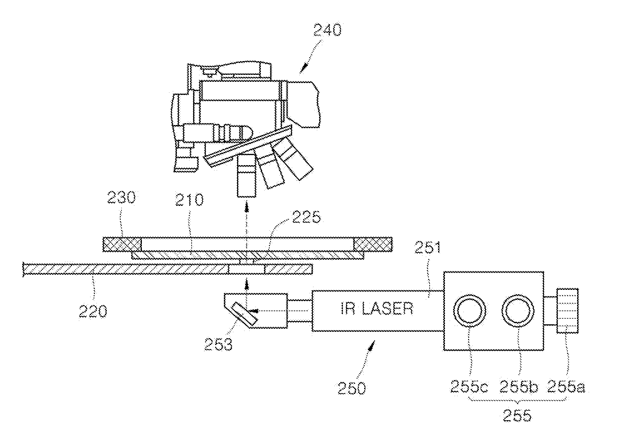
[0014]In the device, the location of a target semiconductor chip to be inspected can be precisely detected using infrared laser light passing through the target semiconductor chip. Therefore, inspection errors caused by faulty information about chip location can be reduced, and a target semiconductor chip can be located quickly. As a result, turn around time (TAT) required for inspection can be largely reduced.
[0016]The device may further include a backside visualization unit that determines whether the infrared irradiation unit is aimed at the target semiconductor chip of the wafer to be inspected. Thus, the infrared irradiation unit can be aligned more precisely and conveniently by using the backside visualization unit.
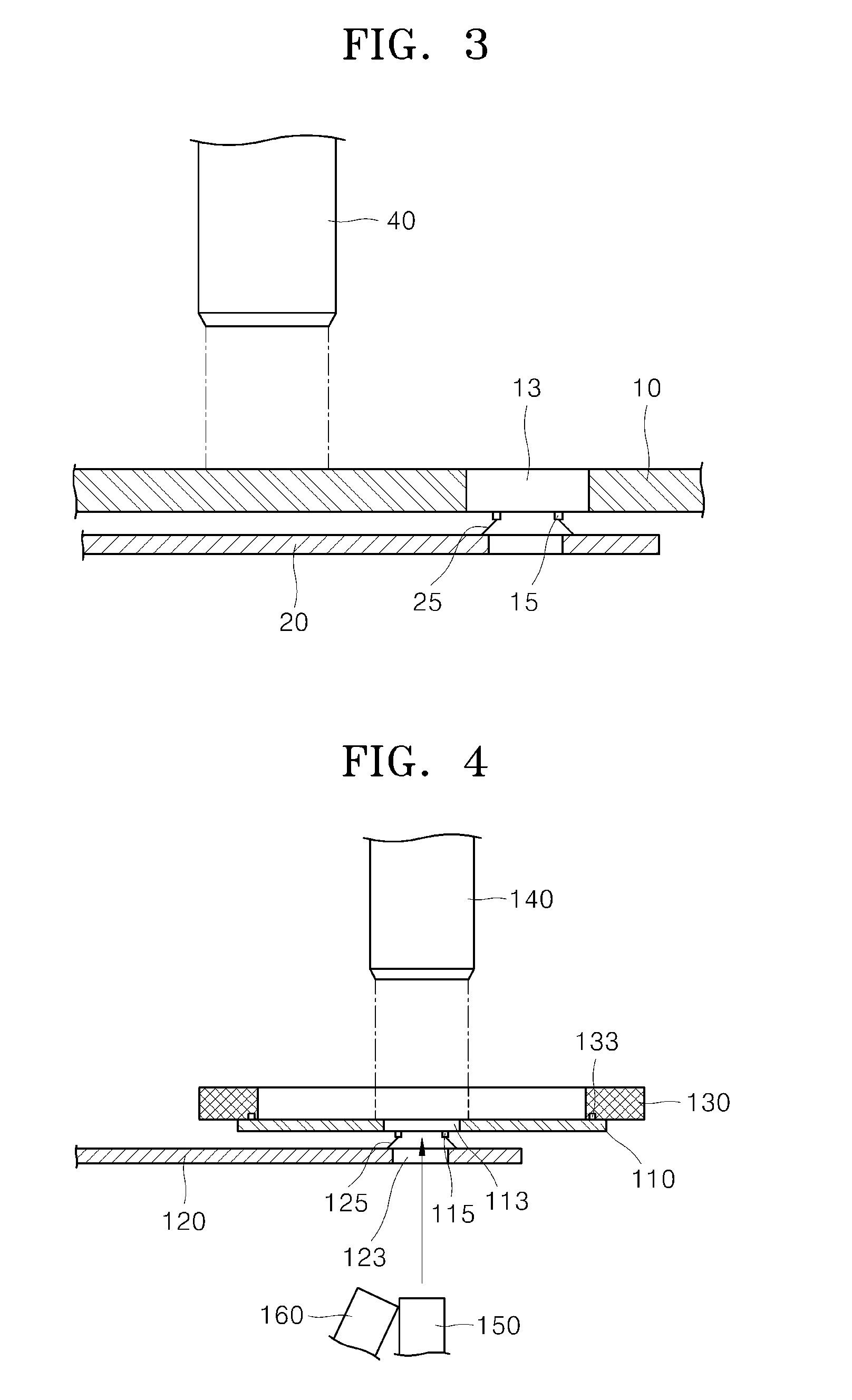
[0017]The device may further include a probe card including an opening and a needle positioned about the opening configured to be electrically connected to a pad of the target semiconductor chip to be inspected. Here, the infrared irradiation unit may irradiate infrared light to the target semiconductor chip through the opening. In this case, the infrared light can be more precisely irradiated to the target semiconductor chip at a right angle, and thus the infrared light can be readily transmitted through the target semiconductor chip.
[0024]In this case, the contacting of the needle and the aiming of the infrared irradiation unit can be performed more precisely and conveniently by using the backside visualization unit.
[0026]In the method, the location of a target semiconductor chip to be inspected can be precisely detected using infrared laser light passing through the target semiconductor chip. Therefore, inspection errors caused by faulty information about chip location can be reduced, and the time for location of a target semiconductor chip can be reduced. As a result, TAT required for inspection can be largely reduced.

Problems solved by technology

This process is manually performed for a relatively long time (about 30 minutes).
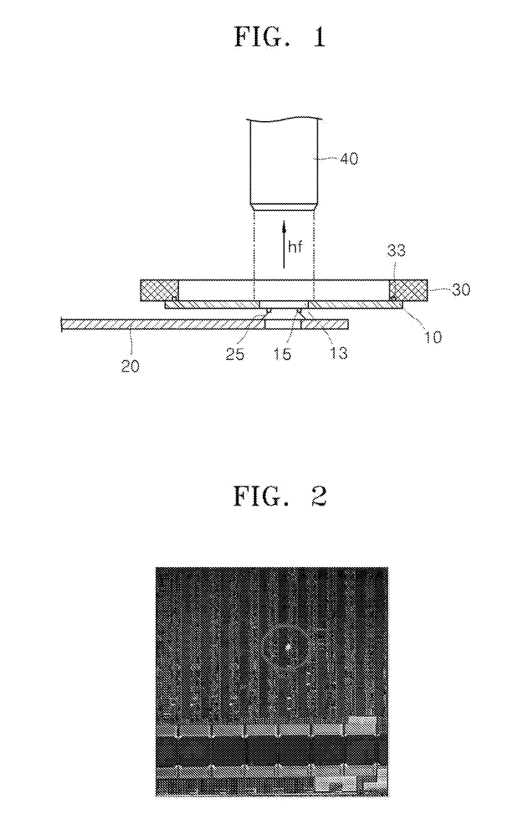
That is, when semiconductor chips formed on a wafer is inspected by an emission method in which the front side of the wafer is oriented in an upward direction, photons generated from a defective transistor formed close to a lower portion of the wafer cannot be observed since the photons are blocked by metal lines formed on the front side of the wafer.

Method used


Image

  • Device for detecting chip location and method of detecting chip location using the device
  • Device for detecting chip location and method of detecting chip location using the device
  • Device for detecting chip location and method of detecting chip location using the device

Examples


Embodiment Construction

[0034]Embodiments of the present invention will now be described more fully with reference to the accompanying drawings, in which exemplary embodiments of the invention are shown. The invention may, however, be embodied in many different forms and should not be construed as being limited to the embodiments set forth herein; rather, these embodiments are provided so that this disclosure will be thorough and complete. In the drawings, like reference numerals in the drawings denote like elements, and elements and regions are schematically drawn.

[0035]It will be understood that when an element is referred to as being “on” another element, it can be directly on the other element or intervening elements may be present. In contrast, when an element is referred to as being “directly on” another element, there are no intervening elements present. As used herein, the term “and / or” includes any and all combinations of one or more of the associated listed items.

[0036]It will be understood that,...


PUM


Abstract

In a device for detecting a chip location and a method of detecting a chip location using the device, the device includes a chuck to which a wafer to be inspected is fixable, an infrared irradiation unit capable of irradiating infrared light to a target semiconductor chip of the wafer from the backside of the wafer, and a scope disposed opposite to the infrared irradiation unit with respect to the wafer. In this manner, it can be readily be determined whether the scope is aligned with a target semiconductor chip to which a probe card is connected for inspection by a backside emission method. Furthermore, the target semiconductor chip to be inspected can be readily detected among semiconductor chips viewed through the scope. Therefore, TAT (turn around time) for inspection can be largely reduced.

Description

CROSS-REFERENCE TO RELATED PATENT APPLICATION[0001]This application claims priority under 35 U.S.C. 119 to Korean Patent Application No. 10-2006-0102472, filed on Oct. 20, 2006, in the Korean Intellectual Property Office, the disclosure of which is incorporated herein in its entirety by reference.BACKGROUND OF THE INVENTION[0002]1. Field of the Invention[0003]The present invention relates to a device for detecting a chip location and a method of detecting a chip location using the device, and more particularly, to a device for determining whether a scope is properly aligned with a semiconductor chip to which a probe card is attached for inspection by a backside emission analysis method and detecting the location of a target semiconductor chip among semiconductor chips viewed through the scope, and a method of detecting the location of a semiconductor chip using the device.[0004]2. Description of the Related Art[0005]Backside emission analysis is used as a method of inspecting semico...

Claims


Application Information

Patent Timeline
Patent Type & Authority Applications(United States)
IPC IPC(8): G01R31/02G01J5/00
CPCG01R31/2891H01L21/681G01R31/311H01L21/68H01L22/00H01L21/02
Inventor LEE, HO-JIN
Owner SAMSUNG ELECTRONICS CO LTD
Learn More