Implant

a technology applied in the field of implants and implants, can solve the problems of bone tissue near the lateral surface of implants, regressing or resorbing, and the effect of bone resorption around implants

Inactive Publication Date: 2008-04-17
ASTRA TECH SE
View PDF19 Cites 3 Cited by
  • Summary
  • Abstract
  • Description
  • Claims
  • Application Information

AI Technical Summary

Benefits of technology

[0021]In embodiments of the inventive concept, the portion of the implant with reduced radius can be provided in many different ways e.g. as patterns along the implant, ring shaped areas around the implant, spot-shaped areas, spiral-shaped areas etc. One of the purposes with the reduced areas / portions is to provide a zone at the implant where the ingrowth is stimulated in a different cycle over time compared to the non-reduced area / portion. Hence, this reduced area / portion cannot be too small due to access of blood and further it is desirable to reduce pressure and stress at the reduced portion to provide a satisfactory bone growth. The same desired effect according to the inventive concept of the invention can alternatively be achieved by providing an enlarged part / portion at the thread making portion, and the in this case the whole implant thread may have the same radius but smaller relative the thread making portion at least in some parts of the thread. The resulting effect is the same as with reduced portions, i.e. there will be areas / portions with no or reduced contact, pressure, stress between the implant and the bone, which will provide a positive influence on the bone growth.
[0049]Preferably a bottom / root, crest, apical or coronal flank of said external fixture thread of said implant is reduced or alternatively combinations thereof. The radius of the root, flank and / or crest is preferably reduced to the same extent, when measured perpendicular to a plane of extension of the flank. This will provide a gap having a substantially uniform distance between the implant and the bone. It is also possible to reduce different portions of the thread profile to achieve the desired effect according to the inventive concept.

Problems solved by technology

One of the major problems relating to successful installation of implants in bone tissue of a patient is the effect of bone resorption around the implant.
This means that the bone tissue in the close proximity of the lateral surface of the implant after implant installation starts to regress or resorb due to necrosis or death of the living bone tissue.
This in turn leads to a poorer stability of the implant, since the implant is not surrounded by as much bone tissue as was intended.
No one has however so far been able to fully explain the mechanisms behind the necrosis and tissue resorption, or later re-growth.

Method used


Image

  • Implant
  • Implant
  • Implant

Examples


Embodiment Construction

[0071]In the following description, reference is made to the figures which show dental implants.

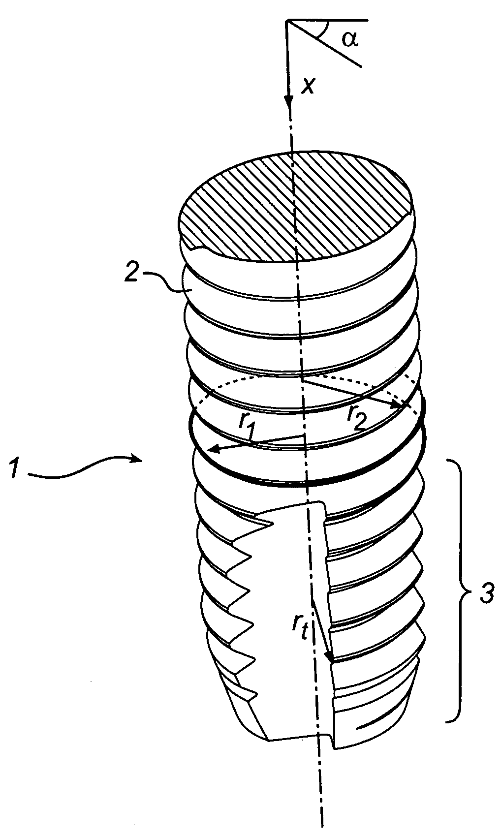
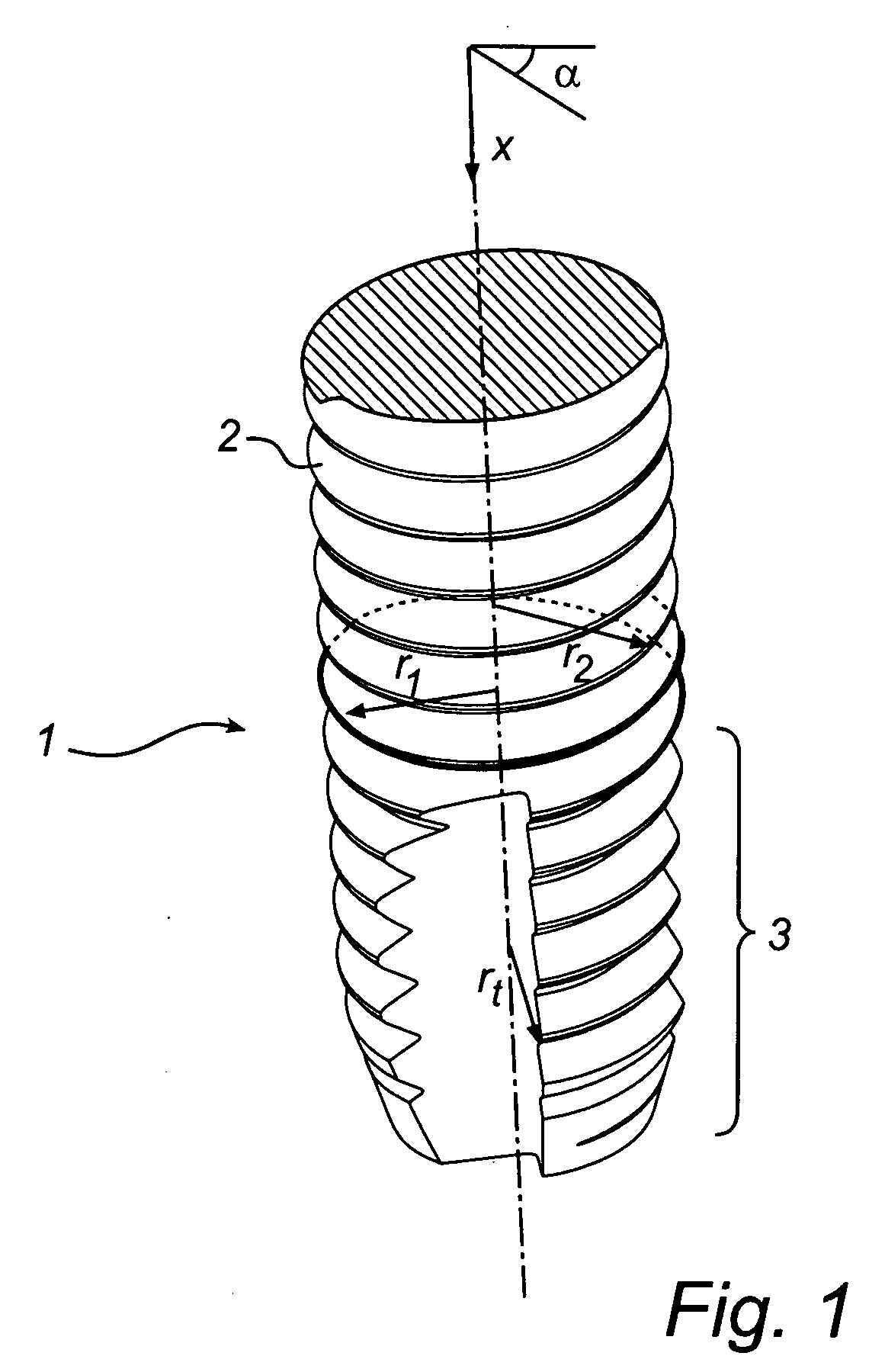
[0072]With reference to FIG. 1, there is shown a dental implant 1 provided with an external fixture thread 2 with an apical thread making means 3 having a radius rt, further the implant is provided with a portion of said thread having a reduced radius r1 and a portion of the thread having a radius r2 being generally equal to the radius rt.

[0073]The expression “radius” is here used for describing the shape of the exterior geometry of the implant 1 (or thread making means 3,3′), i.e. the radius is the distance from the centre axis of the implant 1 to the exterior surface of the thread profile, which distance is variable with the position (x) along the centre axis and the angle position (α) around the implant 1. The radius of the external fixture thread 2 is hence a variable function (f(x,α) of x and α.

[0074]The comparison, of the radius of the first (r1) and second (r2) portions of the exte...


PUM


Abstract

The present invention relates to an implant, an implant set, and a method of implanting an implant. The implant comprises an external fixture thread having a radius, thread making means at an apical end of the external fixture thread for making a bone thread in bone tissue during insertion of the implant. The thread making means having a radius, which radius is generally equal to the radius of a first portion of the external fixture thread. The radius of a second portion of said external fixture thread is further reduced in relation to said radius of said thread making means.

Description

PRIORITY STATEMENT[0001]This application claims the benefit of priority under 35 U.S.C. §119 from European Patent Application No. 06122075.2, filed on Oct. 11, 2006 in the European Patent Office, the disclosure of which is incorporated herein in its entirety by reference.FIELD OF THE INVENTION[0002]The present invention relates to an implant, an implant set, and a method of implanting an implant. The implant comprises an external fixture thread having a radius, thread making means, alternatively a separate thread making means, at an apical end of the external thread for making a bone thread in bone tissue for insertion of the implant.TECHNICAL BACKGROUND[0003]A frequent way today to restore a damaged limb, such as lost tooth, damaged hip joint or finger, is to install an implant in the adjacent bone tissue and replace the damaged parts. In this respect it is of vital importance for a successful result that the implant becomes fully stable and is correctly joined to the bone. The ter...

Claims


Application Information

Patent Timeline
IPC IPC(8): A61B17/00A61B17/08
CPCA61B17/863A61C8/0025A61C8/0022A61B17/8635A61C8/00
Inventor HANSSON, STIG
Owner ASTRA TECH SE
Why Eureka
Try Eureka