Radio Signal Positioning

a radio signal and positioning technology, applied in the direction of duplex signal operation, using reradiation, instruments, etc., can solve the problems of system performance degradation, system suffers significant inaccuracy, system tends to be highly inaccurate in urban environments, etc., to achieve simple and robustness, and accuracy can be made very high

Active Publication Date: 2008-04-17
SAAB AB
View PDF4 Cites 20 Cited by
  • Summary
  • Abstract
  • Description
  • Claims
  • Application Information

AI Technical Summary

Benefits of technology

[0008]The object of the present invention is therefore to provide a simple and robust radio positioning solution, which alleviates the above problems and thus offers output data whose accuracy can be made very high with a reasonable amount of processing.

Problems solved by technology

However, since the GNSS requires a line of sight to multiple satellites, the system tends to be highly inaccurate in urban environments.
Moreover, the system suffers serious performance degradation in the presence of radio channel multipath components.
A calibrated systems based on such fingerprints may attain an accuracy of 1 m. However, the system requires that radio channel and strength measurements be made before the system is established, and its performance is highly environment specific.
Moreover, the system suffers from significant inaccuracies whenever the radio conditions are altered, for example as a result of pedestrian traffic or a change in the room arrangement.
However, such systems are very expensive, require oscillators of exceptionally high accuracy both at the transmitter and the receiver end, and do not operate well in mobile environments.
Furthermore, the design suffers from performance degradation in non-line-of-sight conditions.
However, here the accuracy is limited to 10 m, or worse.
Since this requires an extensive over-sampling, the complexity of the iterative process proposed in the U.S. Pat. No. 5,179,573 increases very rapidly for each correlation iteration.

Method used


Image

  • Radio Signal Positioning
  • Radio Signal Positioning
  • Radio Signal Positioning

Examples


Embodiment Construction

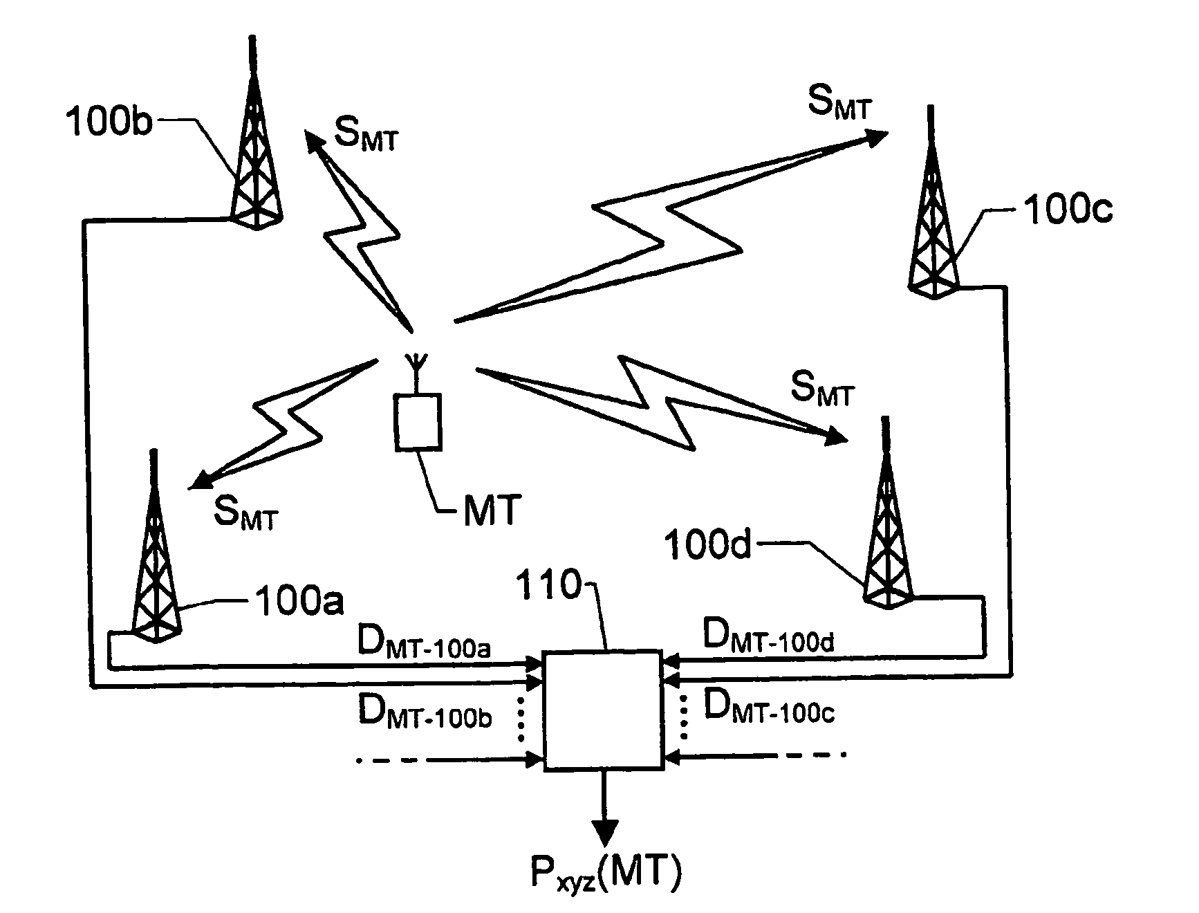
[0032]A proposed system is shown in FIG. 1. Here, a transmitter MT (e.g. a uniquely identifiable unit attached to a soldier) is presumed to be located in an area where a signal SMT transmitted from the transmitter MT can be received by a plurality of sensors, say four, namely 100a, 100b, 100c and 100d respectively. The geographical position of each sensor is known with a high accuracy. According to a preferred embodiment of the invention, each of the sensors 100a, 100b, 100c and 100d determines a respective distance DMT-100a, DMT-100b, DMT-100c and DMT-100d to the transmitter MT based on a registered transmission delay of the signal SMT. The distance data DMT-100a-DMT-100d is then forwarded from the sensors 100a, 100b, 100c and 100d to a central node 110, where the data is collected and used to calculate the transmitter's MT position by means of triangulation or similar technique, and with reference to the positions of the sensors 100a, 100b, 100c and 100d. Generally, the transmitte...


PUM


Abstract

The present invention relates to positioning of a mobile signal transmitter (MT), wherein a respective distance (DMT-100a-DMT-100d) between the transmitter (MT) and each of a plurality of sensors (100a-100d) is determined based on a direct sequence spread spectrum signal (SMT). A transmitter delay of the signal (SMT) is estimated with high accuracy by, in each sensor (100a-100d), cross-correlating an over-sampled representation of the signal (SMT) with an appropriate local spreading sequence (SPP), which contains poly-phased symbol values being different from a set of symbols in the direct sequence used to spread the transmitted signal (SMT). The local spreading sequence (SPP) has a nominal chip period, which is equivalent to the chip period of the over-sampled representation of the signal (SMT).

Description

THE BACKGROUND OF THE INVENTION AND PRIOR ART[0001]The present invention relates generally to positioning of mobile units by means of radio signals. More particularly the invention relates to a method for determining a position of a signal transmitter according to the preamble of claim 1, a sensor according to the preamble of claim 12 and a system according to the preamble of claim 15. The invention also relates to a computer program according to claim 10 and a computer readable medium according to claim11.[0002]In modern life there are many situations in which an accurate positioning of a mobile unit is desirable, for instance in applications concerning freight, transportation, logistics and surveillance or when tracking soldiers and vehicles in a combat training area. In the latter case, the tracking data thus generated may either be used for later simulation or for online monitoring purposes. In any case, due to the normally harsh operating conditions, it is important that the tr...

Claims


Application Information

Patent Timeline
IPC IPC(8): H04B1/707G06F17/15G01S5/06G01S5/14
CPCG01S5/06H04B1/70757H04B1/7075G01S5/14G01S11/02
Inventor OPPERMAN, IAN
Owner SAAB AB
Why Eureka
Try Eureka