
Lens and backlight unit, liquid crystal display having the same and method thereof

a liquid crystal display and backlight technology, applied in the manufacture of electric discharge tubes/lamps, lighting and heating apparatus, instruments, etc., can solve the problems of increased lens cost, increased manufacturing cost of backlight and lcd, and difficulty in packaging leds with lenses

Inactive Publication Date: 2008-04-17
SAMSUNG ELECTRONICS CO LTD
View PDF3 Cites 21 Cited by
  • Summary
  • Abstract
  • Description
  • Claims
  • Application Information

AI Technical Summary

Benefits of technology

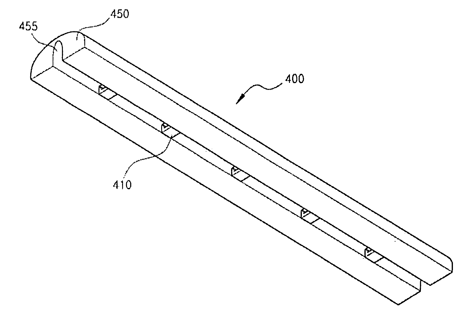
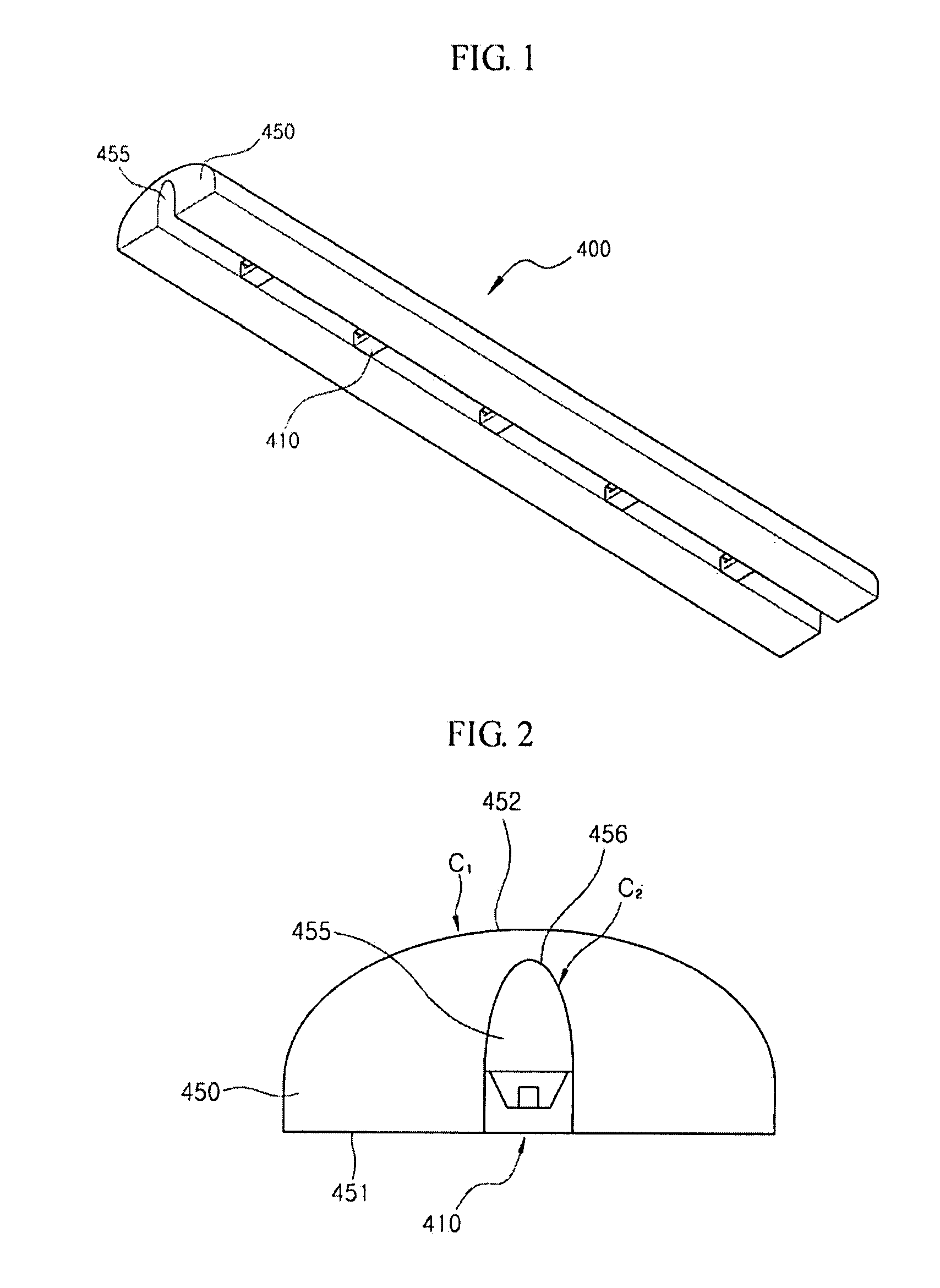
[0007]An exemplary embodiment provides a lens for a liquid crystal display, the lens having a structure of relatively easily disposing a plurality of light sources therein, and a backlight unit and a liquid crystal display having the same.
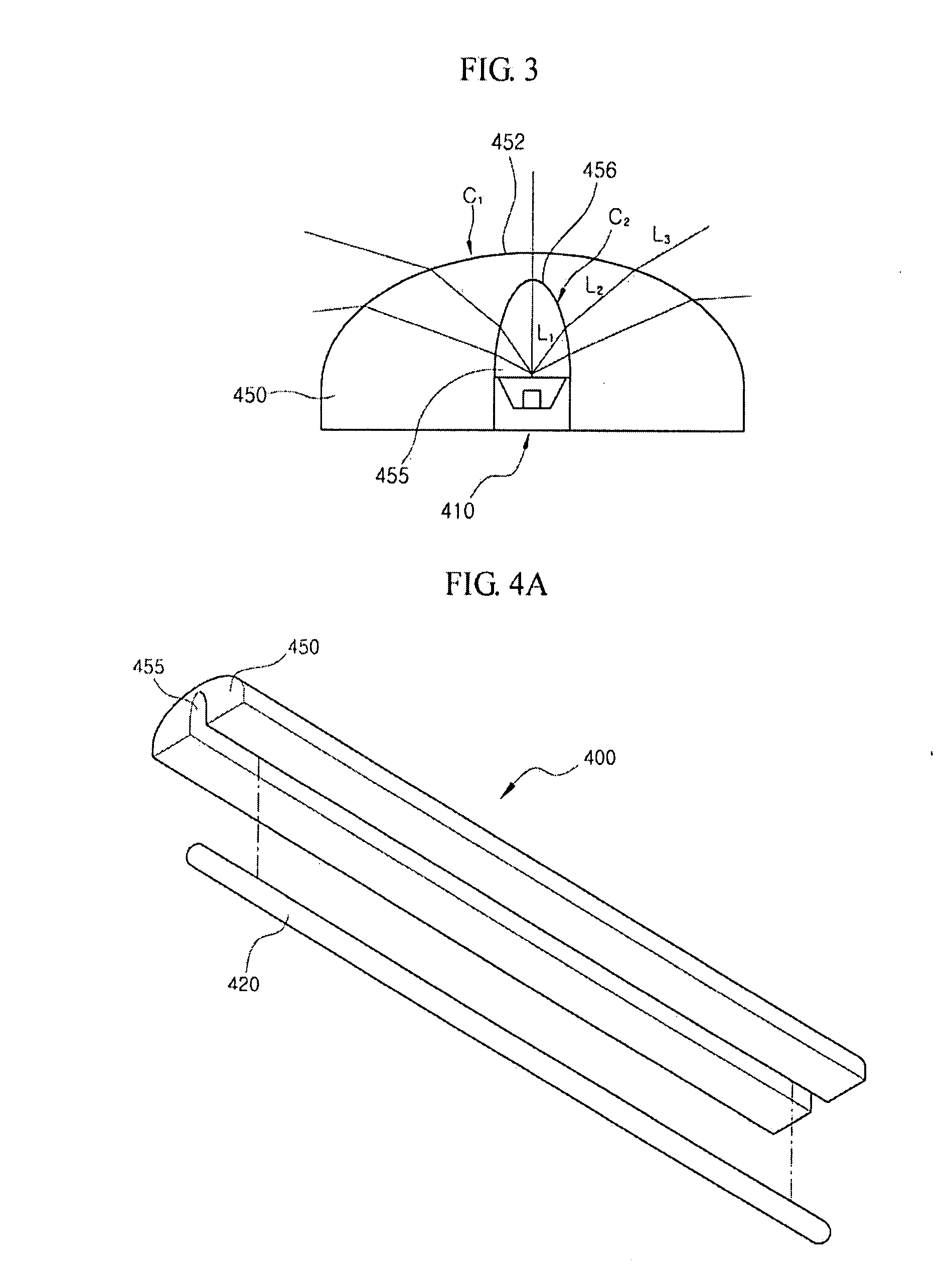
[0008]An exemplary embodiment provides a lens for a liquid crystal display capable of increasing a range of light distribution of a light source and providing uniform illuminance, and a backlight unit and a liquid crystal display having the same.

Problems solved by technology

If the LED is relatively small, it is difficult to package the LED with the lens.
Thus, as a number of LEDs used in an LCD increases, the cost of lenses and the cost for packaging the LEDs with the lenses are accordingly increased.
Consequently, the manufacturing cost of a backlight and an LCD is also increased.

Method used


Image

  • Lens and backlight unit, liquid crystal display having the same and method thereof
  • Lens and backlight unit, liquid crystal display having the same and method thereof
  • Lens and backlight unit, liquid crystal display having the same and method thereof

Examples


Embodiment Construction

[0042]The invention is described more fully hereinafter with reference to the accompanying drawings, in which exemplary embodiments of the invention are shown. This invention may, however, be embodied in many different forms and should not be construed as limited to the exemplary embodiments set forth herein. Rather, these embodiments are provided so that this disclosure will be thorough and complete, and will fully convey the scope of the invention to those skilled in the art. In the drawings, the size and relative sizes of layers and regions may be exaggerated for clarity.

[0043]It will be understood that when all element or layer is referred to as being “on”, “connected to” or “coupled to” another element or layer, the element or layer can be directly on, connected or coupled to another element or layer or intervening elements or layers. In contrast, when an element is referred to as being “directly on,”“directly connected to” or “directly coupled to” another element or layer, the...


PUM

PropertyMeasurementUnit
spaced distanceaaaaaaaaaa
curvatureaaaaaaaaaa
tunnel shapeaaaaaaaaaa

Abstract

A lens for a liquid crystal display, and a backlight unit and a liquid crystal display having the same. The lens for a liquid crystal display includes a flat portion, a curved portion connected with the flat portion, facing the flat portion and including a first curved surface having a first curvature, and a groove disposed in the flat portion and including a second curved surface having a second curvature. The lens and the groove are formed to extend longitudinally in a first direction.

Description

[0001]This application claims priority to Korean Patent Application No. 2006-0099514 filed on Oct. 12, 2006, and all the benefits accruing therefrom under 35 U.S.C. §119, the contents of which are herein incorporated by reference in its entirety.BACKGROUND OF THE INVENTION[0002]1. Field of Invention[0003]The present invention relates to a lens for a liquid crystal display, and a backlight unit and a liquid crystal display having the same, and more particularly, to a lens for a liquid crystal display, which has a structure easy to package a plurality of light emitting diodes, and a backlight unit and a liquid crystal display having the same.[0004]2. Description of the Related Art[0005]As a light source of a backlight for a liquid crystal display (“LCD”), a light bulb, a light emitting diode (“LED”), a fluorescent lamp, a metal halide lamp or the like is generally used. An LED has been widely used as a light source of a backlight for a middle or small LCD, due to long life span, non-n...

Claims


Application Information

Patent Timeline
Patent Type & Authority Applications(United States)
IPC IPC(8): F21S4/00F21V5/04G02F1/1335H01J9/24
CPCG02F1/133603G02B19/0066G02B19/0014G02F1/1335G02B3/00
Inventor HWANG, SEONG YONGYOON, JU YOUNGKIM, GI CHERLKIM, JIN SOOKANG, EUN JEONG
Owner SAMSUNG ELECTRONICS CO LTD
Learn More