
Sheet feeding device and image forming apparatus

a feeding device and a technology of forming apparatus, applied in the direction of transportation and packaging, thin material processing, article separation, etc., can solve the problems of friction coefficient, inability to meet sheets having a different surface condition, inability to feed sheets, etc., to improve the ease of setting of restricting members

Inactive Publication Date: 2008-04-17
CANON KK
View PDF15 Cites 12 Cited by
  • Summary
  • Abstract
  • Description
  • Claims
  • Application Information

AI Technical Summary

Benefits of technology

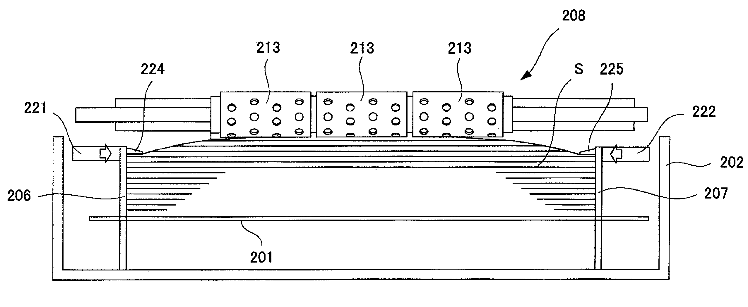
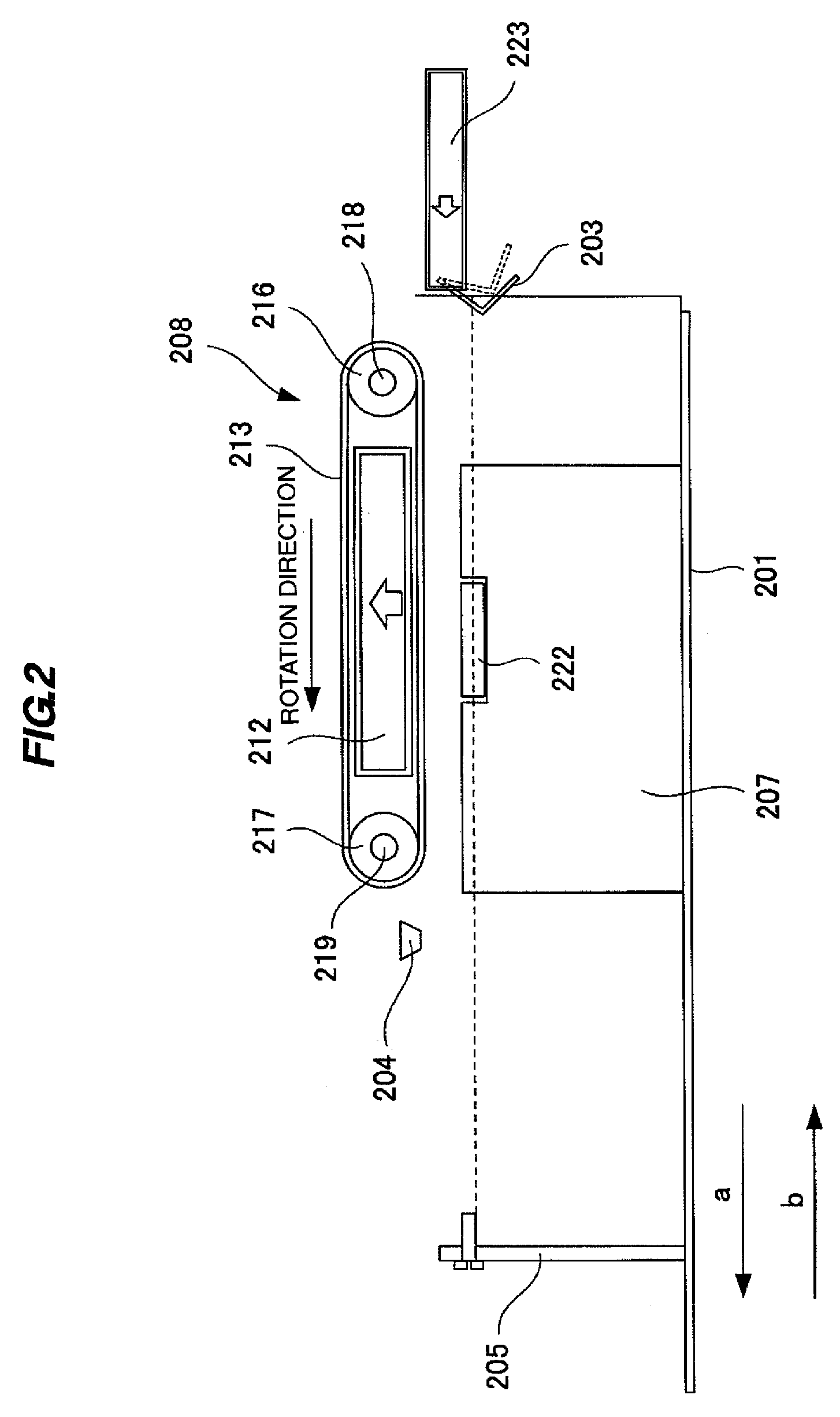
The present invention provides a sheet feeding device for an image forming apparatus that improves the ease of setting the restricting member with the rear end pressing member. The device includes a restricting member, a holding portion, pressing members, and a release mechanism. The restricting member is movable in the sheet storage portion and can be positioned based on the sheet size of the stacked sheets. The pressing members are movable in the vertical direction on the restricting member and can press the top face of the stacked sheets. The release mechanism can hold the restricting member and move the restricting member and pressing members upward from the top face of the stacked sheets. This design makes it easier to set the restricting member and ensures smooth sheet feeding.

Problems solved by technology

Therefore, there are disadvantages such as instability of sheet feeding performance due to changes in friction coefficient of the sheet feeding roller surface because of changes in external shape by friction of the feeding roller, changes of material with a time passage, adhesion of paper powder and the like and inability of meeting sheets having a different surface condition.
Further, because the rear end restricting member does not contact the rear end face of sheets, the position of the sheet in a feeding direction may be dispersed, thereby causing a deviation of sheet feeding timing when the sheet is picked up.

Method used


Image

  • Sheet feeding device and image forming apparatus
  • Sheet feeding device and image forming apparatus
  • Sheet feeding device and image forming apparatus

Examples


Embodiment Construction

[0031]Hereinafter, a preferred embodiment for carrying out the present invention will be described in detail with reference to the accompanying drawings.

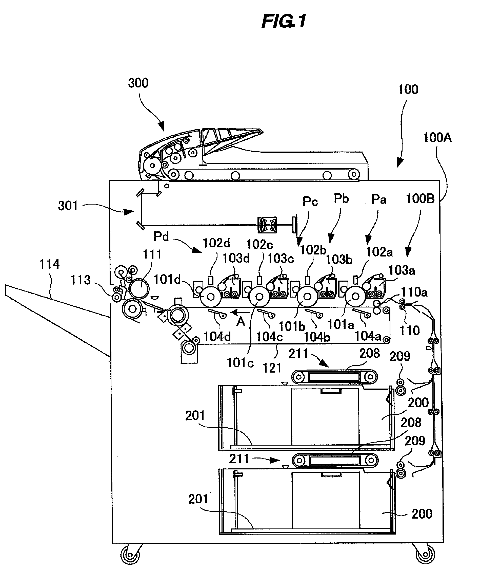
[0032]FIG. 1 is a diagram showing a schematic structure of a color laser printer which is an example of an image forming apparatus equipped with a sheet feeding device according to the embodiment of the present invention. In FIG. 1, a color laser printer 100, a color laser printer main body 100A (hereinafter referred to as printer main body), an image reading portion 300 and a scanner 301 are shown.

[0033]This printer main body 100A includes an image forming portion 100B for forming an image on a sheet and a sheet feeding device 21 for feeding the sheet to the image forming portion 100B.

[0034]The image forming portion 100B is provided with process stations Pa-Pd for forming four colors of toner images, yellow (Y), magenta (M), cyan (C) and black (Bk). The process stations Pa-Pd include photosensitive drums 101 (101a-101d) which are i...


PUM


Abstract

The position of a sheet accommodated in a sheet storage portion is restricted by a restricting member provided movably on a sheet storage portion. This restricting member has a holding portion which is movable freely and is attached detachably to the sheet storage portion so as to hold the restricting member at a restricted position corresponding to a sheet size. The end portion of the sheet whose rear end position is restricted is pressed from above by a pressing member provided movably in a vertical direction on the end portion restricting member. Then, to move the restricting member, an operation portion is operated and the holding portion is moved in a direction of releasing the engagement and the pressing member is raised upward of accommodated sheets.

Description

BACKGROUND OF THE INVENTION[0001]1. Field of the Invention[0002]The present invention relates to a sheet feeding device and an image forming apparatus, and more particularly to a restricting member for restricting the end portion of sheets accommodated in a sheet storage portion.[0003]2. Description of the Related Art[0004]Conventionally, the image forming apparatus such as a copying machine, electrophotographic printer, ink jet printer, facsimile machine, printing machine is equipped with a sheet feeding device for feeding sheets one by one from a sheet storage portion which accommodates a plurality of sheets.[0005]Generally, such a sheet feeding device feeds sheets stacked on a sheet stack tray by rotation friction of sheet feeding rollers whose surface is composed of rubber or the like. In this type, the feeding performance largely depends on friction coefficient of the surface of the sheet feeding roller. Therefore, there are disadvantages such as instability of sheet feeding pe...

Claims


Application Information

Patent Timeline
Patent Type & Authority Applications(United States)
IPC IPC(8): B65H3/08
CPCB65H3/128B65H3/48B65H3/54B65H2511/20B65H2701/1313B65H2220/02B65H2220/11B65H2405/11425
Inventor KUSHIDA, HIDEKI
Owner CANON KK
Learn More