
Tramway transit system

Active Publication Date: 2008-04-10
MITSUBISHI HEAVY IND ENG LTD
View PDF3 Cites 36 Cited by
  • Summary
  • Abstract
  • Description
  • Claims
  • Application Information

AI Technical Summary

Benefits of technology

[0028] The present invention was made in light of the background mentioned above, and the object is to provide a tramway transit system with fail-safe function in which a vehicle provided with guard wheels travels while automatically steered on a pre-established track provided with a protection track, simplification in construction and weight saving of the automatic steering mechanism, and space saving for the installation of the mechanism, can be attained, and reaction force exerted on the automatic steering mechanism caused by reaction force which the guard wheels receive from the protection track due to contact of the wheels with the protection track when malfunction occurs in the automatic steering mechanism, is reduced, and stable traveling of the vehicle is secured.

Problems solved by technology

The mechanical guide mechanism is superior in point of view of safety and reliability, however, structure of bogies to which the wheels and driving mechanism thereof are mounted inevitably becomes complicated, is increased in weight, and results in increased running cost.
Further, it is necessary to lay down the guide rail having enough strength to support the guide rails all along the tramway with high accuracy, so vast amounts of construction cost of the tramway is needed.
Further, as wear-out parts such as guide wheels are not used, maintenance cost is decreased.
However, according to the steering system disclosed in the patent literature 1, as mechanical steering by means of the guide rail and guide wheels is not provided, it is difficult to secure safety of vehicle traveling against runaway and running out of track when malfunction occurs in the steering system and under abnormal circumstances caused by strong wind, rainfall, snowfall, etc.
However, is no system with which above mentioned problems are solved sufficiently by a compact and weight saving construction and effective high speed operation can be made possible.
The actuator of this construction is simple in structure, however, large reaction force exerts on the guard wheels and steering mechanism when the guard wheels contact the protection track caused by malfunction of the steering mechanism or disturbances, which may induce damage of the guard wheels or occurrence of deformations of constituent parts of the steering mechanism and shorten the life of the guard wheels or add to wear of the constituent parts of the steering mechanism.
Therefore, a large underfloor space is required to accommodate these devices including piping, maintenance of the devices and piping is necessary, and particularly care and attention must be paid concerning oil leaks.
Reaction force the guard wheels receive from the protection track when the guard wheels contact with the protection track caused by malfunction of the steering mechanism or disturbances can be reduced by lowering pressure in the air circuit, however, retard in controlling tends to occur.
Further, steering by means of guard wheels when malfunction occurs in the steering mechanism is unstable as is in the case of the oil hydraulic servo cylinder.

Method used


Image

  • Tramway transit system
  • Tramway transit system
  • Tramway transit system

Examples


first embodiment

The First Embodiment

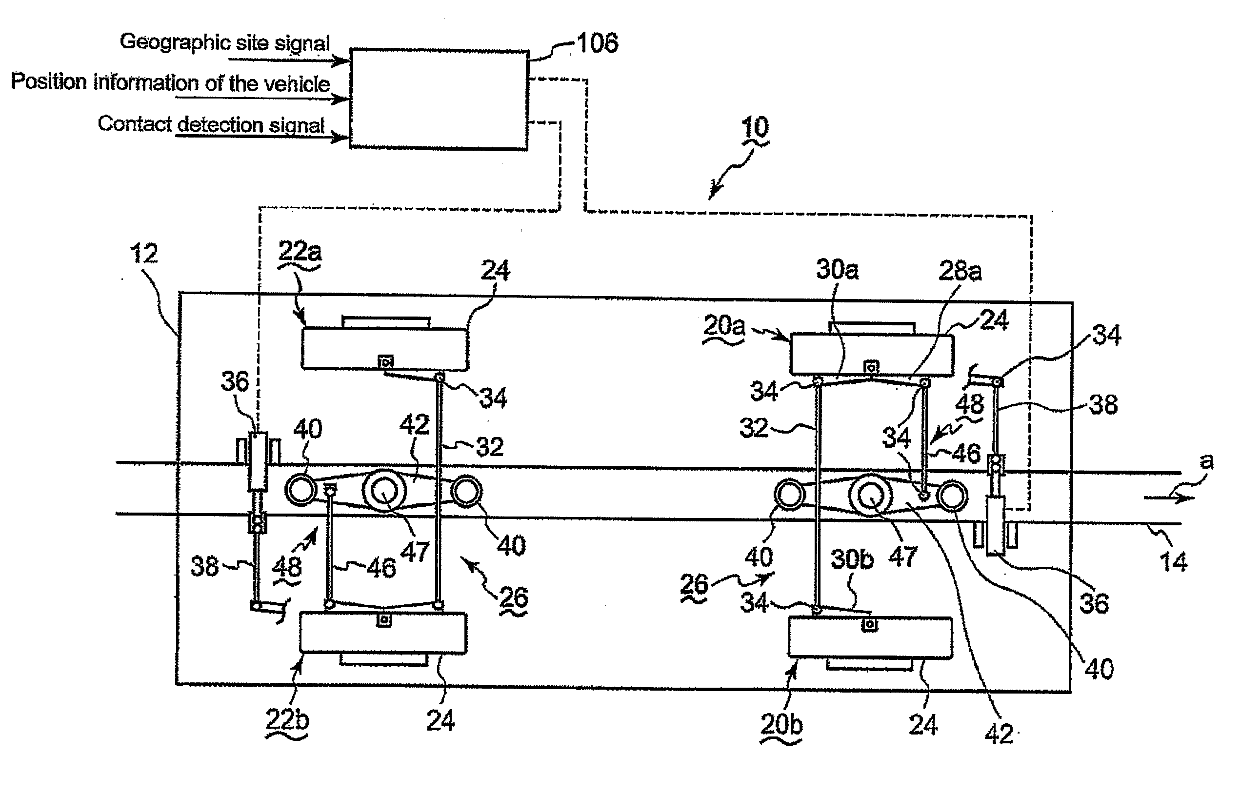
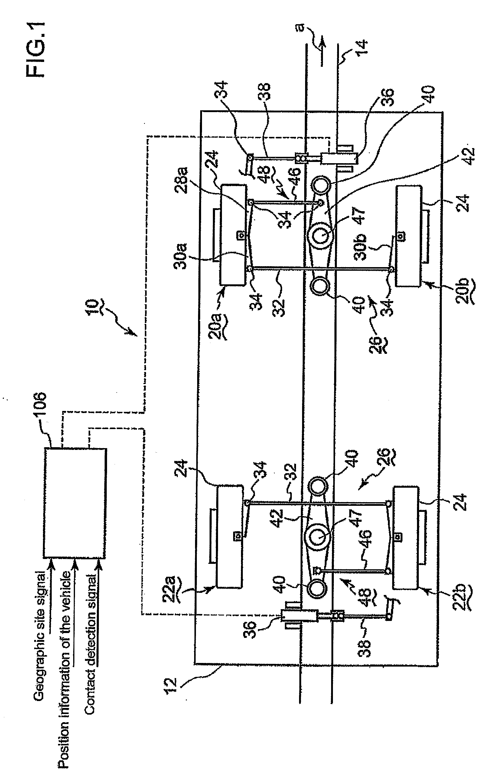
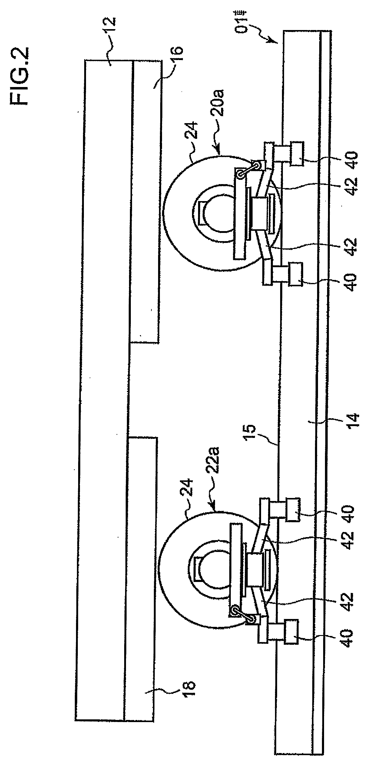
[0062] Referring to FIGS. 1-3 showing the first embodiment of the tramway transit system 10 of the invention, a tramway vehicle 12 runs along a track 01. The track is composed such that a protection track 14 having a groove of U-shaped cross section is provided on the road surface 15 of the track 01 along the center thereof.

[0063] The vehicle 12 runs in direction a. The vehicle 12 has a front bogie 16 and a rear bogie 18 under the vehicle body. A front axle 44 of front wheels 20 and a rear axle (not shown in the drawings) of rear wheels 22 are attached to the front bogie 16 and rear bogie 18 respectively rotatable in right and left directions. The front and rear wheels have rubber tires not shown distinctly in the drawing.

[0064] Next, a steering mechanism 26 for front wheels 20 will be explained. As to a steering mechanism 26 for rear wheels 20 is the same in construction to that of the front one, and explanation is omitted.

[0065] As shown in FIGS. 1-3, to a l...

second embodiment

The Second Embodiment

[0117] Next, a second embodiment is explained referring to FIGS. 11 and 12. The second embodiment is a modification of the first embodiment, and constituents the same to those of the first embodiment are indicated by the same reference numerals, of which explanation is omitted.

[0118] As shown in FIG. 11, The fundamental structure of the steering mechanism 26 is similar to the first embodiment. The second embodiment is constructed by adding to the first embodiment restoration spring devices 124, and other than this is the same to the first embodiment. Each of the restoration spring devices 124 is a device comprising a spring member, a coil spring for example, to push the protector arm 42 in order to allow the guard wheels 40 to take a central position in the protection track 14.

[0119] According to the embodiment, when malfunction occurs in the automatic steering mechanism 26 and the vehicle is steered guided by the guard wheels 40, the protector arm 42 is allow...


PUM


Abstract

A tramway transit system for allowing a vehicle to travel along a track while automatically steered is proposed, in which the vehicle is provided with guard wheels and the track is provided with a protection track, and simplification in construction and weight saving of the automatic steering mechanism provided to the vehicle and space saving for the installation of the mechanism, can be attained. The vehicle (12) is provided with a steering mechanism (26) for steering the front and rear wheels (20, 22) by means of electrically driven oil hydraulic actuators 36, the protection track (14) is laid down on the road surface (15) of the track (01), the vehicle (12) is provided with guard wheels (40), and the interlocking mechanism (48) for connecting the guard wheels to the right or left wheels, the actuator (36) comprising the hydraulic cylinder (60), the two-way discharge pump (76), the variable speed, reversible rotation motor (78), and the closed circuit (82) provided with relief valves (86).

Description

BACKGROUND OF THE INVENTION [0001] 1. Field of the Invention [0002] The present invention relates to a tramway transit system in which vehicles having wheels equipped with for example rubber tires travel on a pre-established tramway, specifically relates to an actuator of an automatic steering mechanism of the vehicle. [0003] 2. Description of the Related Art [0004] A vehicle supported by wheels with rubber tires for a new transit system is generally provided with guide wheels so that the vehicle is steered to travel along the tramway, the steering being usually done mechanically through the guide wheels engaging with a guide rail laid along the tramway. [0005] The mechanical guide mechanism is superior in point of view of safety and reliability, however, structure of bogies to which the wheels and driving mechanism thereof are mounted inevitably becomes complicated, is increased in weight, and results in increased running cost. Further, it is necessary to lay down the guide rail ha...

Claims


Application Information

Patent Timeline
IPC IPC(8): E01B25/00
CPCE01B25/28B62D1/265
Inventor MORITA, KATSUAKIYAMAGUCHI, MASAHIROKATAHIRA, KOSUKE
Owner MITSUBISHI HEAVY IND ENG LTD
Learn More