
Heat pipe and manufacturing method thereof

a manufacturing method and technology of heat pipe, applied in indirect heat exchangers, semiconductor/solid-state device details, lighting and heating apparatus, etc., can solve the problems of increasing the number of transistors deployed in a unit area of an electronic element, affecting heat-conducting efficiency, long joint between two plates, etc., to simplify the manufacturing process and simplify the manufacturing process.

Inactive Publication Date: 2008-04-03
DELTA ELECTRONICS INC
View PDF3 Cites 18 Cited by
  • Summary
  • Abstract
  • Description
  • Claims
  • Application Information

AI Technical Summary

Benefits of technology

The present invention provides a flat heat pipe and a manufacturing method that simplifies the manufacturing process by eliminating complicated manufacturing elements. The flat heat pipe includes a hollow annular body with two open ends, a wick structure, and two bending portions that form a sealed space within the hollow annular body. The sealed space is filled with a working fluid. The hollow annular body is integrally formed as a single piece by extruding or drawing, and the bending portions are formed at the open ends by a jig. The hollow annular body may include at least one support member that increases the intensity and area of the wick structure. The flat heat pipe contacts a heat source, such as an electronic device, to transmit heat. The technical effects of the invention include simplifying the manufacturing process, reducing manufacturing costs, and improving heat transfer efficiency.

Problems solved by technology

Increased numbers of transistors deployed in a unit area of an electronic element produce considerable heat during operation.
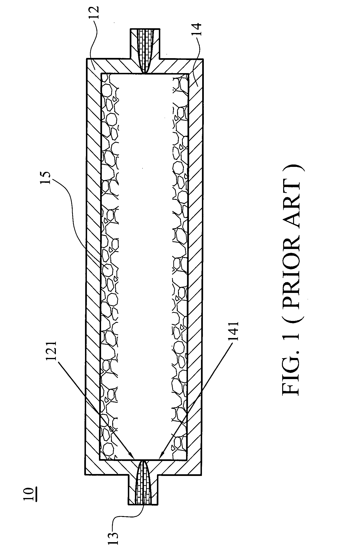
However, the discontinued sections 121, 141 of wick structure not only block the path of heat conduction, but also affect heat-conducting efficiency of the plate heat pipe 10.
The welding joint between two plates is long and unreliable, and further causes discontinuity of the wick structure on the inner surface of the plates.
Furthermore, conventional welding of upper and lower plates increases costs for both materials and fabrication.

Method used


Image

  • Heat pipe and manufacturing method thereof
  • Heat pipe and manufacturing method thereof
  • Heat pipe and manufacturing method thereof

Examples


Embodiment Construction

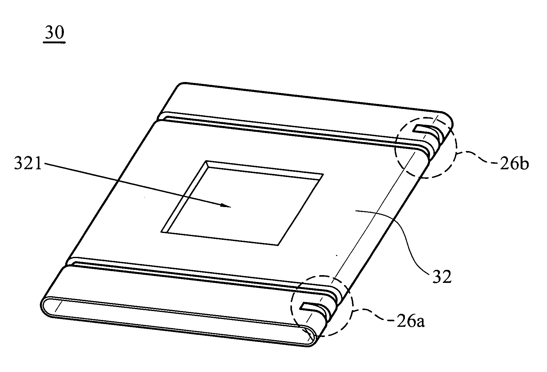
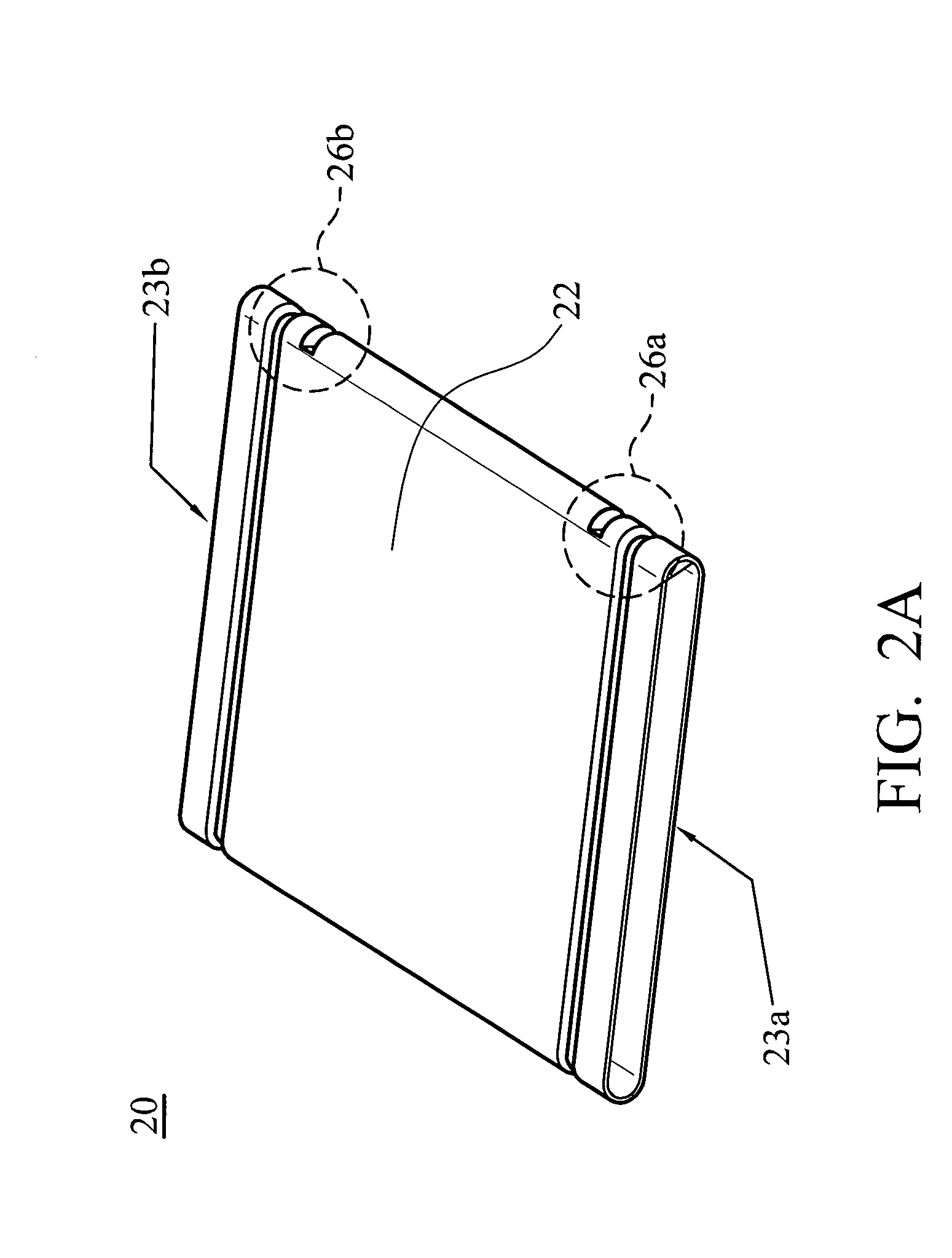
[0029]Referring to FIGS. 2A and 2C; FIG. 2A is a schematic view of an embodiment of a flat heat pipe of the invention, and FIG. 2C is a sectional view of the flat heat pipe in FIG. 2A. In FIG. 2A, a flat heat pipe 20 includes a hollow annular body 22, which is flat, with two open ends 23a, 23b. A wick structure 25 is formed between an inner surface of the hollow annular body 22. Two bending portions 26a, 26b are disposed at the two open ends 23a, 23b, respectively, to form a sealed space 27 within the hollow annular body 22. A working fluid 28 is filled in the sealed space 27.

[0030]Referring to FIGS. 2A and 2B; FIG. 2B is an enlarged view of a bending portion of the flat heat pipe in FIG. 2A. The annular body 22 is integrally formed as a single piece by extruding or drawing. The bending portions 26a, 26b are respectively formed at the two open ends 23a, 23b of the annular body 22 by a jig, such as a punching machine, allowing a sealed space 27 to be formed in the annular body 22, as...


PUM

PropertyMeasurementUnit
heat-conductiveaaaaaaaaaa
areaaaaaaaaaaa
energyaaaaaaaaaa

Abstract

A heat pipe includes a hollow annular body with two open ends and two bending portions. A wick structure is formed at an inner surface of the annular body. The bending portions are respectively disposed at the two open ends to form a sealed space within the hollow annular body. A working fluid is filled in the sealed space. Also, a method of manufacturing a heat pipe including steps of: providing a hollow annular body with two open ends, and a wick structure is formed at an inner surface of the hollow annular body; and forming two bending portions respectively at the two open ends to form a sealed space within the hollow annular body, and a working fluid is filled in the sealed space.

Description

BACKGROUND OF THE INVENTION[0001]This Non-provisional application claims priority under U.S.C. § 119(a) on Patent Application No(s). 095136196, filed in Taiwan, Republic of China on Sep. 29, 2006, the entire contents of which are hereby incorporated by reference.[0002]1. Field of the Invention[0003]The present invention relates to a heat pipe and a manufacturing method thereof, and in particular to a flat heat pipe with low cost and high efficiency.[0004]2. Description of the Related Art[0005]Increased numbers of transistors deployed in a unit area of an electronic element produce considerable heat during operation. Heat pipes provide a simple and effective heat dissipation solution, and are thus widely used. Heat dissipation is achieved by way of energy transmitted through the phase change between gas and liquid of a working fluid. During vaporization, the working fluid removes heat energy from a heat source. Vapor produced fills a vacuum within the pipe. During condensation, vapor...

Claims


Application Information

Patent Timeline
Patent Type & Authority Applications(United States)
IPC IPC(8): H05K7/20F28D15/02
CPCB23P15/26B23P2700/09F28D15/0233F28D15/0283F28D15/046H01L23/427H01L2924/0002Y10T29/49353H01L2924/00
Inventor CHUNG, MING-TELIN, CHI-FENGCHEN, CHIN-MING
Owner DELTA ELECTRONICS INC
Learn More