
Heat-conductive dielectric polymer material and heat dissipation substrate containing the same

a dielectric polymer and heat dissipation substrate technology, applied in the direction of thermoplastic polymer dielectrics, dielectric characteristics, plastic/resin/waxes insulators, etc., can solve the problem of affecting the heat dissipation efficiency affecting the intensity of the emitted light and the lifetime, and affecting the workability of the heat dissipation substrate, so as to achieve the effect of enhancing the workability and heat dis

Active Publication Date: 2008-03-27
POLYTRONICS TECH
View PDF7 Cites 23 Cited by
  • Summary
  • Abstract
  • Description
  • Claims
  • Application Information

AI Technical Summary

Benefits of technology

[0006]An aspect of the present invention is to provide a heat-conductive dielectric polymer material, which has an inter-penetrating-network (IPN) structure and is rubbery, thereby enhancing its workability and heat dissipation property.

Problems solved by technology

However, in high-power LEDs used for illumination, only about 15%-20% of the power inputted into the LED is converted into light, while the remaining 80%-85% is converted into heat, and the heat cannot be dissipated to the environment at the appropriate time.
Thus, the interfacial temperature of the LED component is excessively high, thereby affecting the intensity of the emitted lights and the lifetime.
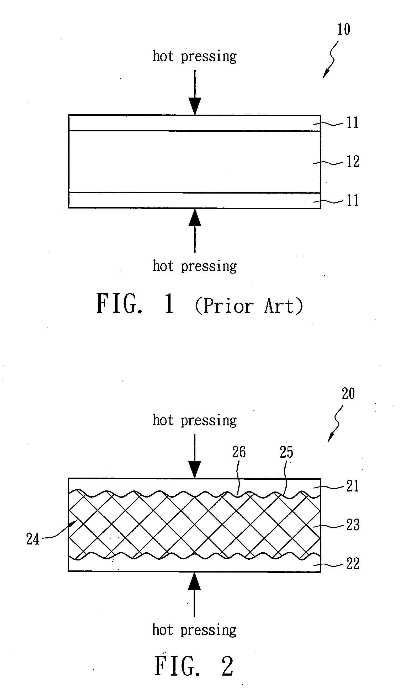
However, the conventional art is limited by the property of the slurry and has the following disadvantages: (1) the conventional art must be finished within a specific time; otherwise, the slurry will cure and cannot be coated on the metal foil, causing a waste of the slurry; and (2) when the hot pressing step is conducted in the conventional art, a quantity of slurry flows out of the two metal foils 11, and a separation between solid and liquid occurs upon reaching the hot pressing temperature, thus, the electrically conductive filler is non-uniformly distributed in the dielectric heat-conductive material layer 12, thereby affecting the heat dissipation efficiency of the heat dissipation substrate 10.
Furthermore, as for the slurry, it is difficult to store and the flexibility of the process for forming the heat dissipation substrate is limited by the viscosity of the slurry (e.g., heat dissipation substrates with different shapes cannot be fabricated efficiently).

Method used


Image

  • Heat-conductive dielectric polymer material and heat dissipation substrate containing the same
  • Heat-conductive dielectric polymer material and heat dissipation substrate containing the same

Examples


Embodiment Construction

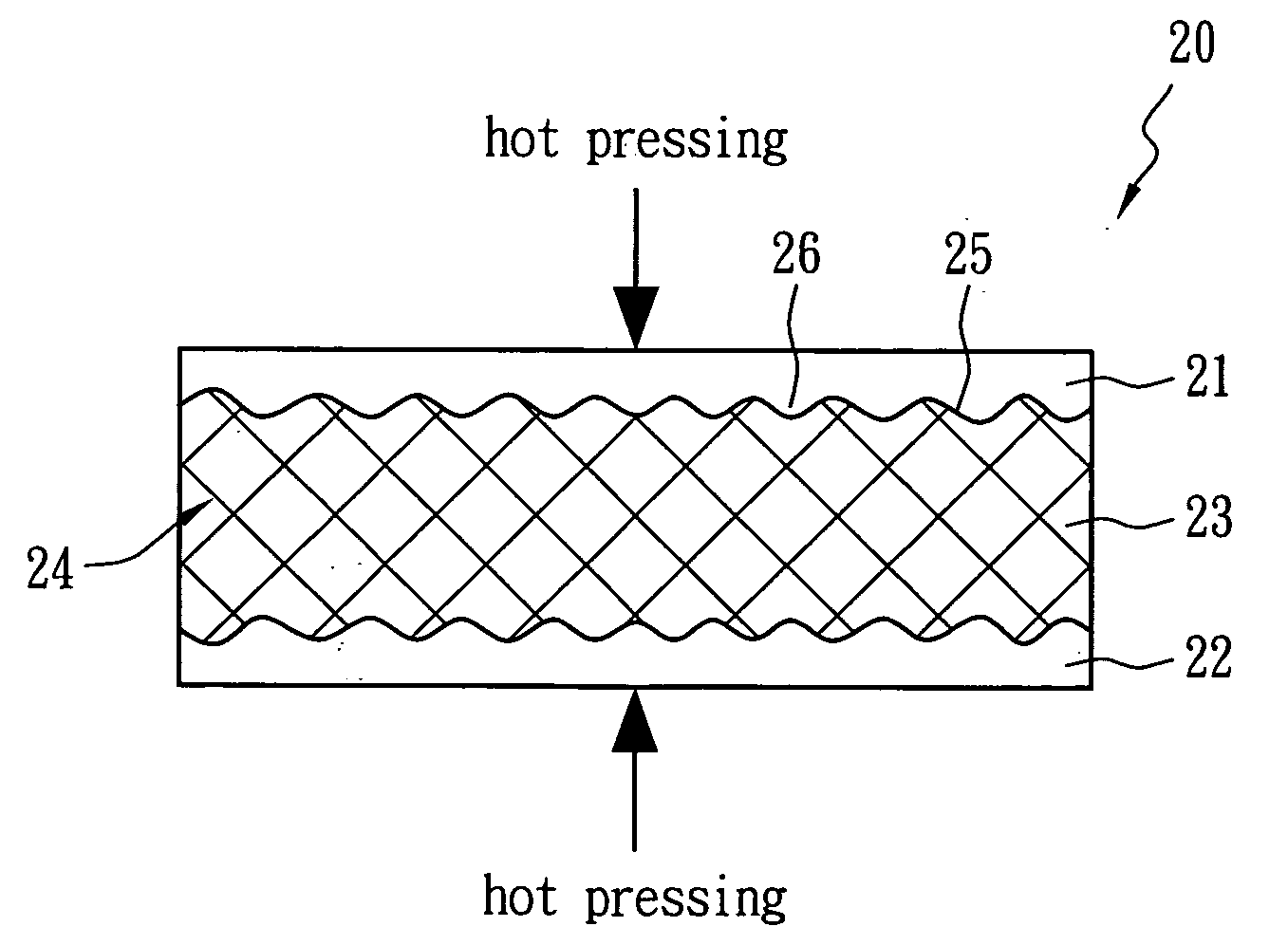
[0012]The heat-conductive dielectric polymer material of the present invention includes a polymer component, a curing agent, and a heat-conductive filler having an IPN structure. The polymer component includes a thermoplastic plastic and a thermosetting epoxy resin; calculated on the basis of volume percentage, the thermosetting epoxy resin comprises 10% to 75% of the polymer component. The curing agent is used to cure the thermosetting epoxy resin under a curing temperature. The heat-conductive filler is uniformly dispersed in the polymer component; calculated on the basis of volume percentage, it comprises 40% to 70% of the heat-conductive dielectric polymer material. The heat conductivity of the heat-conductive dielectric polymer material is larger than 0.5 W / mK.

[0013]FIG. 2 is a schematic view of a heat dissipation substrate 20 of the present invention. The heat dissipation substrate 20 includes a first metal layer 21, a second metal layer 22, and a heat-conductive dielectric po...


PUM

PropertyMeasurementUnit
temperatureaaaaaaaaaa
voltageaaaaaaaaaa
thicknessaaaaaaaaaa

Abstract

A heat-conductive dielectric polymer material having an inter-penetrating-network (IPN) structure includes a polymer component, a curing agent, and a heat-conductive filler uniformly dispersed in the polymer component. The polymer component includes a thermoplastic plastic and a thermosetting epoxy resin. The curing agent is used to cure the thermosetting epoxy resin at a curing temperature. The heat conductivity of the heat-conductive dielectric polymer material is larger than 0.5 W / mK. A heat dissipation substrate including the heat-conductive dielectric polymer material in the present invention has a thickness of less than 0.5 mm and bears a voltage of over 1000 volts.

Description

FIELD OF THE INVENTION[0001]The present invention relates to a heat-conductive dielectric polymer material and a heat dissipation substrate including the heat-conductive dielectric polymer material, and more particularly to a heat-conductive dielectric polymer material having an inter-penetrating-network (IPN) structure and a heat dissipation substrate including the heat-conductive dielectric polymer material.DESCRIPTION OF THE PRIOR ART[0002]Recently, the light emitting diode (LED) has gained considerable attention worldwide as an important new technology with broad applications and numerous benefits. LED technology offers the advantages of having a small volume, low power consumption, long lifetime, a favorable reaction speed, and overcomes many of the problems of incandescent lamps. LED technology is used in many applications, including backlights for the LCD displays, mini-projectors, illuminators and light sources for vehicles, attracting increasing attention.[0003]However, in ...

Claims


Application Information

Patent Timeline
Patent Type & Authority Applications(United States)
IPC IPC(8): H01B3/48
CPCH01B3/006H01B3/40H05K1/0373H05K2201/10106H05K2201/0129H05K2201/0209H05K2201/09309H05K1/189Y10T428/31515Y10T428/31529Y10T428/31522C08L63/00C08K9/04
Inventor WANG, DAVID SHAU CHEWYANG, EN TIENYU, JYH MINGCHU, FU HUA
Owner POLYTRONICS TECH
Learn More