
Iterative decoder employing multiple external code error checks to lower the error floor

a decoding and error floor technology, applied in the field of iterative decoding performance of communication systems, can solve the problems of not iterative decoding of serial concatenated code, inability to achieve the optimal overall composite system for a given concatenated code, and often limited transmitter power and spectrum availability of communication systems

Inactive Publication Date: 2008-03-20
ENTROPIC COMM INC
View PDF7 Cites 23 Cited by
  • Summary
  • Abstract
  • Description
  • Claims
  • Application Information

AI Technical Summary

Problems solved by technology

Communication systems are often limited in terms of transmitter power and spectrum availability.
Not all of such serially concatenated codes are iteratively decoded in practice, however.
However, in practice, this serial concatenated code is not iteratively decoded.
However, although each decoder may be optimal for its specific task, the overall composite system may not be optimal for a given concatenated code.
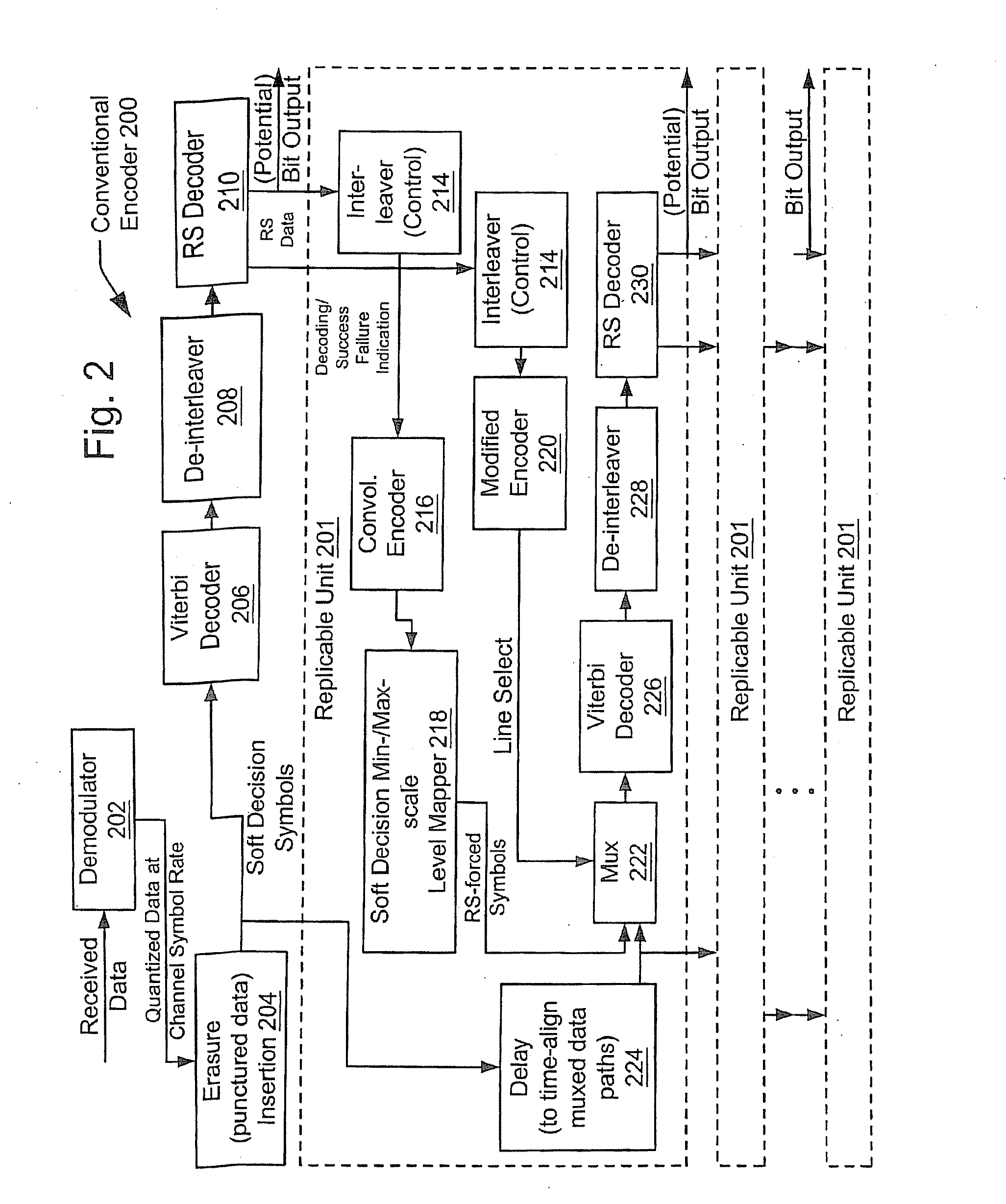
One problem in such decoding processes is determining how the Viterbi algorithm is to be modified to accommodate inputs from Reed-Solomon decoded blocks that are correct.
A limitation of conventional turbo decoders is the inability to reach very low bit error rate (BER) floors; this inhibits their broad application to video transport, which requires very low BERs.
These approaches try to make more efficient the already existent methods of trying to perform turbo decoding, but sometimes practical implementations that achieve the desired level of performance are difficult to find.
For some applications, whereby only the turbo code is used, one may not be able to achieve sufficiently low BER floors as desired or required within a given application.

Method used


Image

  • Iterative decoder employing multiple external code error checks to lower the error floor
  • Iterative decoder employing multiple external code error checks to lower the error floor
  • Iterative decoder employing multiple external code error checks to lower the error floor

Examples


Embodiment Construction

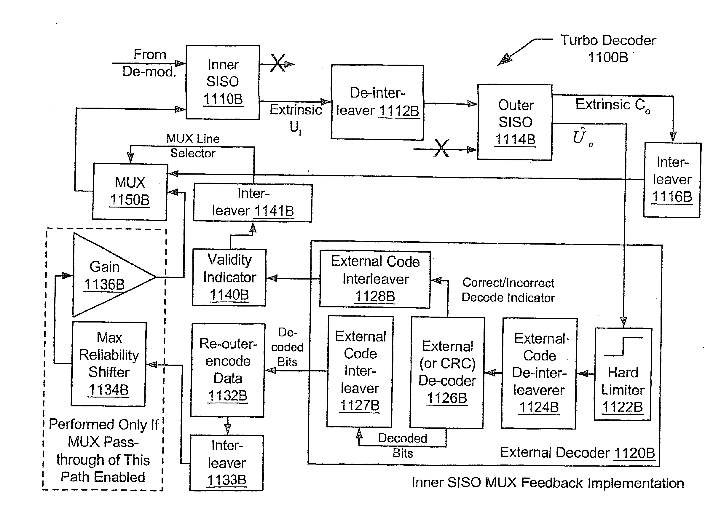
[0042] One example of digital video processing is that employed using the motion picture expert group (MPEG) standard. In the MPEG standard, a block consists of 188 bytes of data. In one embodiment of the present invention, the turbo decoding system operates on nominally 10 MPEG blocks of source data in a turbo decoder frame. A cyclic redundancy check (CRC) check is contained within each of these MPEG blocks. One purpose of the CRC check is to ensure that the MPEG decoder has advance knowledge of whether the bits that it is receiving are correct or not. A turbo decoder operable in accordance with the present invention is able to take advantage of the redundancy of the CRC to further improve the decoding performance. During iterations before the final iteration, this improvement in decoding performance is achieved.

[0043] From one perspective, when a block covered by a CRC (henceforward, a “CRC block”) decodes correctly, it may be assumed with a relative high degree of certainty that...


PUM


Abstract

Iterative decoder employing multiple external code error checks to lower the error floor and / or improve decoding performance. Data block redundancy, sometimes via a cyclic redundancy check (CRC) or Reed Solomon (RS) code, enables enhanced iterative decoding performance. Improved decoding performance is achieved during interim iterations before the final iteration. A correctly decoded CRC block, indicating a decoded segment is correct with a high degree of certainty, assigns a very high confidence level to the bits in this segment and is fed back to inner and / or outer decoders (with interleaving, when appropriate) for improved iterative decoding. High confidence bits may be scattered throughout inner decoded frames to influence other bit decisions in subsequent iterations. Turbo decoders typically operate relatively well at regions where the BER is high; the invention improves iterative decoder operation at lower BERs, lowering the ‘BER floor’ that is sometimes problematic with conventional turbo decoders.

Description

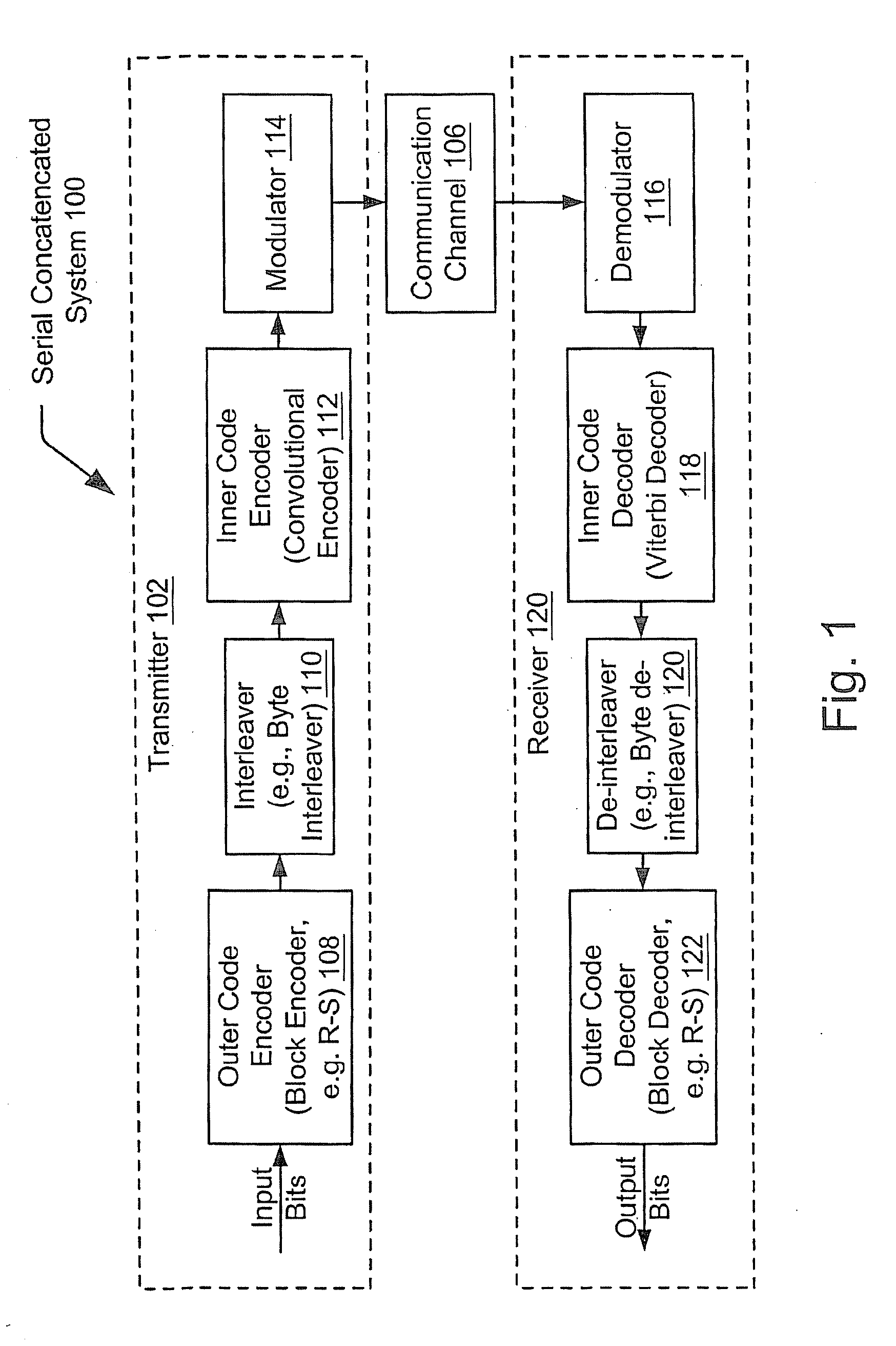
[0001] This application is a continuation of U.S. application Ser. No. 10 / 892,738, filed Jul. 16, 2004; which is a continuation of U.S. application Ser. No. 09 / 865,958, filed May 25, 2001; which is a continuation-in-part of U.S. application Ser. No. 09 / 492,962 filed Jan. 28, 2000, now U.S. Pat. No. 6,606,724; the above-identified applications are incorporated herein by reference in their entirety.TECHNICAL FIELD [0002] The present invention relates generally to communication systems and iterative decoding performance. A method and apparatus for decoding the serial concatenation of multiple external code blocks with serially concatenated block- and convolutional-coded data is presented. An example of how these concepts may be applied to parallel concatenated codes is also presented. BACKGROUND [0003] Communication systems are often limited in terms of transmitter power and spectrum availability. For these and other reasons, it is often a goal of digital communications design to maxim...

Claims


Application Information

Patent Timeline
Patent Type & Authority Applications(United States)
IPC IPC(8): H03M13/03G06F11/00H03M13/09H03M13/15H03M13/29H04L1/00
CPCH03M13/09H03M13/15H03M13/2936H03M13/2948H03M13/2972H04L1/0066H03M13/3994H04L1/005H04L1/0054H04L1/0061H04L1/0065H03M13/3776
Inventor EIDSON, DONALD BRIANKRIEGER, ABRAHAMMURALI, RAMASWAMY
Owner ENTROPIC COMM INC
Learn More