
Particulate matter removal apparatus

a technology of removing apparatus and particulate matter, which is applied in the direction of filtration separation, auxillary pretreatment, separation process, etc., can solve the problems of difficult to handle the filter, cracked or melted filters, and high cost of ceramic honeycomb filters, so as to increase the performance of the filter material, the effect of reducing the amount of thermal energy required to regenerate the filter

Inactive Publication Date: 2008-03-20
NISSIN ELECTRIC CO LTD
View PDF19 Cites 33 Cited by
  • Summary
  • Abstract
  • Description
  • Claims
  • Application Information

AI Technical Summary

Benefits of technology

[0015] Exemplary embodiments of the present invention provide a particulate matter removal apparatus which is excellent in durability and significantly reduces electricity consumed for heating, burning and removing the thus captured particulate matter. [First Invention (Filter / Heater / Heat Insulating Material)]

Problems solved by technology

However, ceramic honeycomb filters are expensive and cannot be readily replaced when they are damaged.
Since the ceramic honeycomb filter has a great number of hard wall surfaces, there is a case where the filter may be cracked or melted due to intensive thermal stress or localized heating at the time of heating, burning and removing the thus trapped particulate matter.
In preventing the above damage of ceramic honeycomb filters, it is necessary to monitor the state of gases, estimate the status of particulate matter captured by the filter and make a complicated linkage with the control of the engine, thereby making it quite difficult to handle the filter, which is a problem.
However, a related-art ceramic fiber filter is disadvantageous in that the capturing efficiency of particulate matter is lower than a filter composed of ceramic honeycomb structures.
Further, the thus captured particulate matter is heated by an electric heater and oxidized, burned and removed, thereby necessitating greater electricity, which is another problem.
Therefore, ease in heat conduction is controlled by rendering the heat conduction difficult under conditions of k / d≦50 W / m2K or k / d≦20 W / m2K.
The filter is required to be difficult in heat conduction and low in thermal capacity.

Method used


Image

  • Particulate matter removal apparatus
  • Particulate matter removal apparatus
  • Particulate matter removal apparatus

Examples


embodiment 1

Embodiment 1 (Embodiment of the First Invention)

embodiment 1-1 (fig.5 , fig.6)

[Embodiment 1-1 (FIG. 5, FIG. 6)]

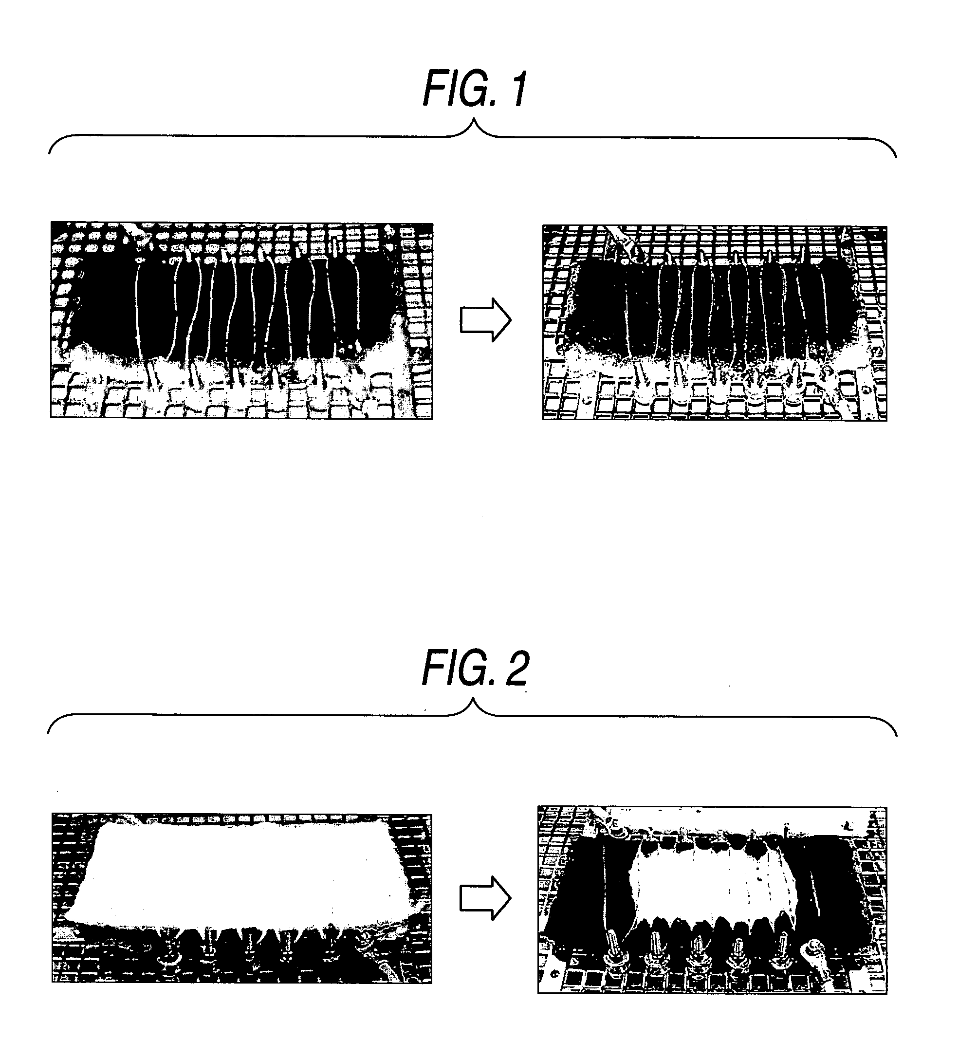
[0155]FIG. 5 and FIG. 6 show Embodiment 1 of the first invention. FIG. 5 shows a state in which exhaust gases are filtered and clarified, and FIG. 6 shows a state in which a filter is regenerated. More specifically, FIG. 5 illustrates a first constitution of the present invention, that is, the exhaust gas filtration apparatus in which a ceramic fiber filter is provided parallel with a channel of exhaust gas, a heat insulating material of ceramic fibers is fixed so as to face the filter, an electric heater is provided between the filter and the heat insulating material, an on-off valve is provided at a gas inlet. This is a sectional view showing a state that the on-off valve of the apparatus is opened, thereby allowing exhaust gas to flow (filtration). FIG. 6 illustrates a first constitution of the present invention, that is, the exhaust gas filtration apparatus in which a ceramic fiber filter is provided parallel with a channel of exhaust gas, a heat...

embodiment 1-2 (fig.7 , fig.8)

[Embodiment 1-2 (FIG. 7, FIG. 8)]

[0186]FIG. 7 shows another embodiment of the first invention of the present invention. This embodiment is similar in fundamental structure to that illustrated in FIG. 5, but designed to use a single member in place of a heat insulating material and an on-off valve arranged in close proximity to a filter. The heat insulating material is required for arrangement in close proximity to the filter only when the filter is heated and regenerated. Therefore, such necessity may be taken into account in constituting the apparatus.

[0187]FIG. 7 shows a state at the time of filtration, and FIG. 8 shows a state at the time of regeneration. More specifically, FIG. 7 illustrates a second constitution of the present invention, that is, the exhaust gas filtration apparatus in which a ceramic fiber filter is provided on a channel of exhaust gas, an electric heater is provided at a entry port of the ceramic fiber filter, and a heat insulating material is provided so as...


PUM

PropertyMeasurementUnit
thicknessaaaaaaaaaa
densityaaaaaaaaaa
linear velocityaaaaaaaaaa

Abstract

A filter is made with heat-insulating ceramic fibers, and where the filter is increased in pressure loss due to particulate matter captured after filtration of exhaust gas, gas flow is blocked, a heating element is used to heat the surface of the filter, thereby burning and removing particulate matter. The filter is of heat insulating properties, by which a heat insulating material is arranged near the particulate matter capturing face of the filter, and the heating element is incorporated between the surface of the filter and the heat insulating material. The filter can be regenerated at a higher heating efficiency in a smaller quantity of thermal energy. The heat insulating material is also used as a filter, by which the apparatus can be made more compact. A charging element is arranged upstream of the filter material, by which the filter material is increased in particulate matter capturing performance, thereby suppressing the rate of increase in the pressure loss and improving heating efficiency of particulate matter.

Description

[0001] This application claims priority to Japanese Patent Application No. 2006-242357, filed Sep. 7, 2006, in the Japanese Patent Office. The priority application is incorporated by reference in its entirety. TECHNICAL FIELD [0002] The present disclosure relates to an apparatus for capturing and removing particulate matter (PM) in gases exhausted from diesel engines, etc. Diesel engines, which have been widely used as engines for large vehicles, are driven by using light oil or heavy oil as fuel and are highly fuel efficient. Diesel engines are not provided with an ignition spark plug unlike a gasoline engine. The diesel engine is higher in compression ratio, causing ignition by blowing a mist of compressed light oil or heavy oil into the engine. Diesel engines are advantageous, for example, high in thermal efficiency, large in displacement volume, great in power and long in service period. [0003] However, exhaust gases from diesel engines are responsible for serious environmental ...

Claims


Application Information

Patent Timeline
Patent Type & Authority Applications(United States)
IPC IPC(8): B01D41/00B03C3/01
CPCB01D46/0063F01N3/01F01N3/0226F01N2390/02F01N2240/04F01N2290/02F01N3/0275B01D46/84B03C3/41B03C3/60B03C3/62B03C3/155B03C2201/30B03C2201/12B03C3/49B03C3/12B03C3/38B03C3/70B03C2201/04B03C3/025B03C3/06F01N3/021F01N3/02
Inventor NAITO, KENTASENBAYASHI, SATORUHAMADA, YUICHI
Owner NISSIN ELECTRIC CO LTD
Learn More