
System and method for pre-defined wake-up of high speed serial link

Inactive Publication Date: 2008-03-13
NOKIA CORP
View PDF13 Cites 48 Cited by
  • Summary
  • Abstract
  • Description
  • Claims
  • Application Information

AI Technical Summary

Benefits of technology

[0009]Various exemplary embodiments of the invention provide apparatus and method for transmi

Problems solved by technology

However, this approach requires additional circuit and logic at the transmitter to set differential signal to an illegal state and at the receiver side to detect the illegal stage from the differential line.
However, since the high-speed serial transfer interface allows current to constantly flow through the transmitter circuit and the receiver circuit, reducing power consumption is typically only possible by sending information in burst mode and switching off the link after every data transmission.
The use of such high voltage swing links creates several problems.
Further, the high voltage swing link approach becomes difficult or impossible to implement when the high-speed signal is transmitted over optical fiber where there are no separate links to provide power up and power down control and signaling.

Method used


Image

  • System and method for pre-defined wake-up of high speed serial link
  • System and method for pre-defined wake-up of high speed serial link
  • System and method for pre-defined wake-up of high speed serial link

Examples


Embodiment Construction

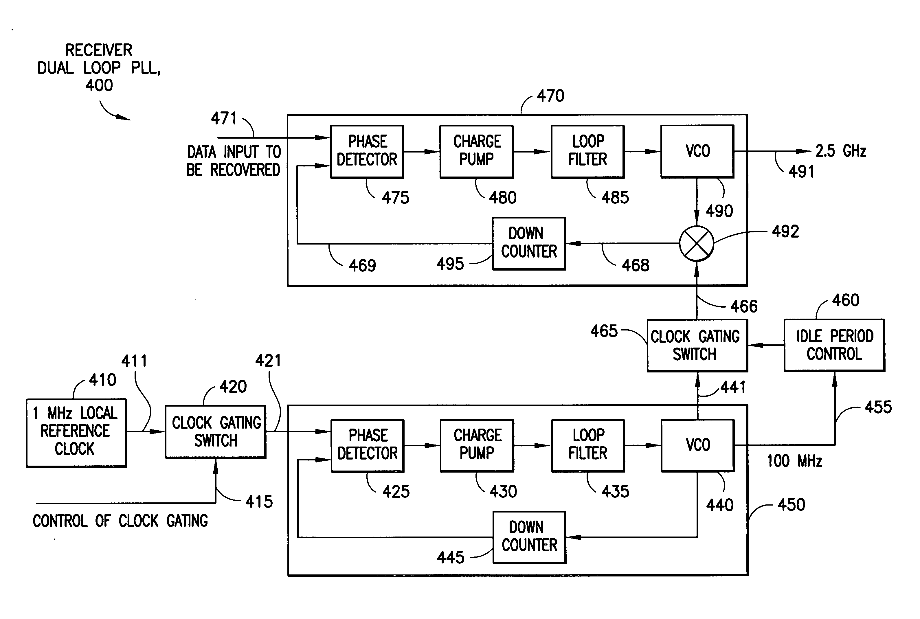
[0028]Various exemplary embodiments of this invention describe method and apparatus for transmitting and receiving data through a high-speed, low-power serial interface. The high-speed serial interface can achieve power saving by power up and power down operations without using high voltage swing control signaling.

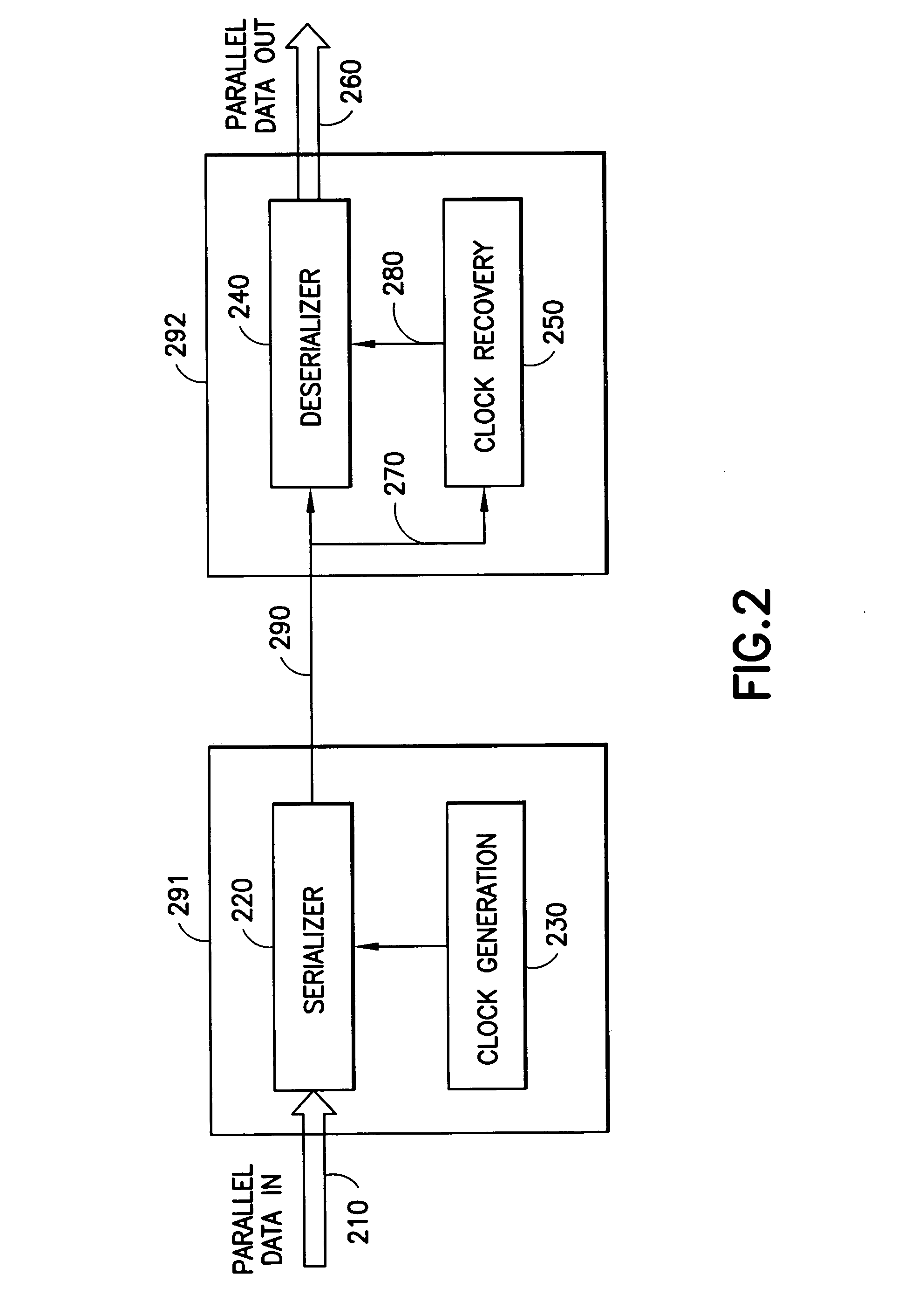
[0029]FIG. 2 shows a block diagram of the serial interface which includes a transmitter 291, a channel 290, and a receiver 292. Parallel data input 210, typically 8, 16 or 32 bits wide, applies data to a serializer 220. A PLL based clock generation circuit 230 is utilized to provide a high speed clock signal for the serializer 220. The serialized data may be encoded into 8B10B format (8B10B encoder is not shown in FIG. 1) to help clock recovery, reduce inter-symbol interference generated timing jitter and provide error detection. The serialized data is then transmitted through the channel 290, typically differential pair cable or optical fiber. The serialized data from cha...


PUM


Abstract

A system and method for transmitting and receiving through a high speed serial link with power up and power down capability. The exemplary embodiments of this invention involves a method of power up and power down the high-speed serial link without using high voltage swing control and signaling. Both the transmitter and the receiver wake up only during pre-defined burst cycles. During each burst cycle, data will be transmitted and received in burst mode. Outside each burst cycle, the transmitter and receiver will be powered off or partially powered off. Various phase-locked loop based circuit ensure the transmitter and the receiver can be locked in frequency and phase quickly at the time of power-up. The duration of the burst cycle and the interval between two adjacent burst cycles can be either fixed or changed by upper level protocol.

Description

FIELD OF THE INVENTION[0001]The exemplary embodiments of this invention relate generally to data communication. In particular, the exemplary embodiments of this invention relate to transmission of data over a high-speed serial link between two subsystems of a data communication system.BACKGROUND OF THE INVENTION[0002]This section is intended to provide a background or context to the exemplary embodiments of this invention. The description herein may include concepts that could be pursued, but are not necessarily ones that have been previously conceived or pursued. Therefore, unless otherwise indicated herein, what is described in this section is not prior art to the description and claims in this application and is not admitted to be prior art by inclusion in this section.[0003]A high-speed serial transfer interface such as Low Voltage Differential Signaling (LVDS) has attracted attention as an interface standard aiming at reducing Electro Magnetic Interference (EMI), thermal and ot...

Claims


Application Information

Patent Timeline
IPC IPC(8): H03D3/24H04L7/00
CPCH03L7/0802H04L7/0337H03L7/23H04W52/028Y02D30/70
Inventor VOUTILAINEN, MARTTI
Owner NOKIA CORP
Learn More