
Method and System for Adaptively Setting a Transmitter Filter for a High Speed Serial Link Transmitter

a technology of serial link and filter, applied in the field of communication systems, can solve the problems of limiting the transmission speed between the transmitter and the receiver, and affecting the performance of the signal, and achieving the effect of reducing the bandwidth limitation of the signal, and reducing the bandwidth limitation

Inactive Publication Date: 2011-10-13
AVAGO TECH INT SALES PTE LTD
View PDF13 Cites 7 Cited by
  • Summary
  • Abstract
  • Description
  • Claims
  • Application Information

AI Technical Summary

Benefits of technology

[0011]Various advantages, aspects and novel features of the present invention, as well as details of an illustrated embodiment thereof, will be more fully understood from the following description and drawings.
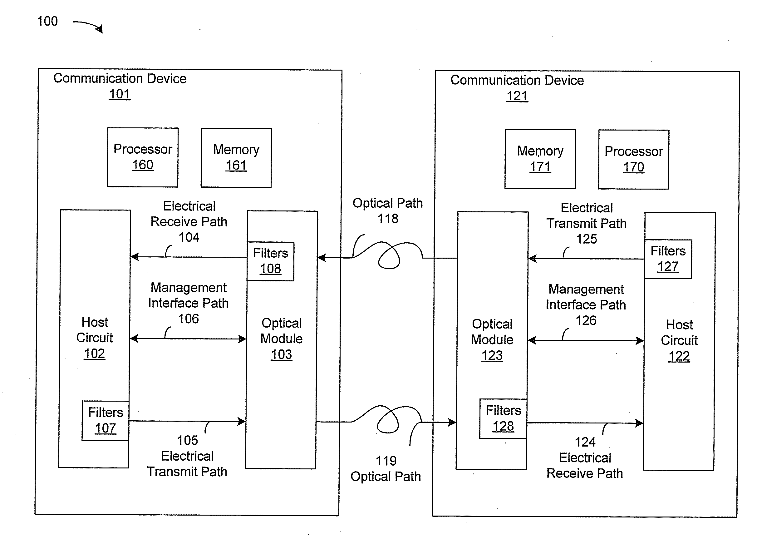
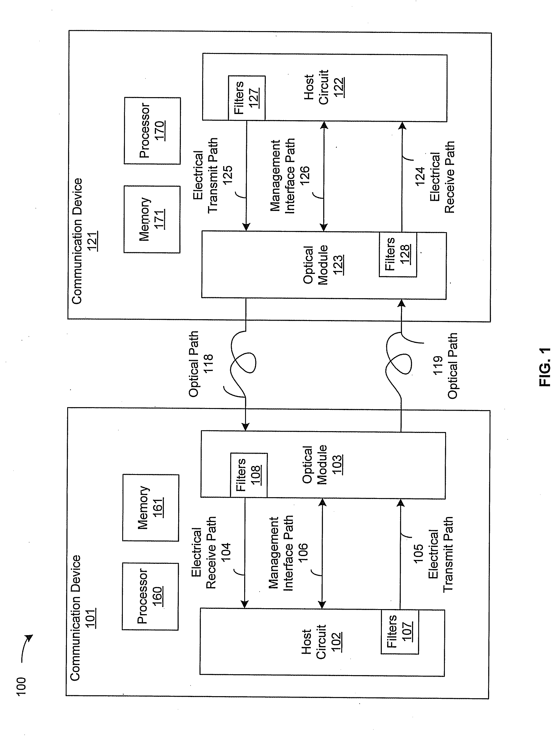
[0012]FIG. 1 is a block diagram illustrating an exemplary communication system that is operable to adaptively set a transmitter filter for a high speed serial link transmitter, in accordance with an embodiment of the invention.
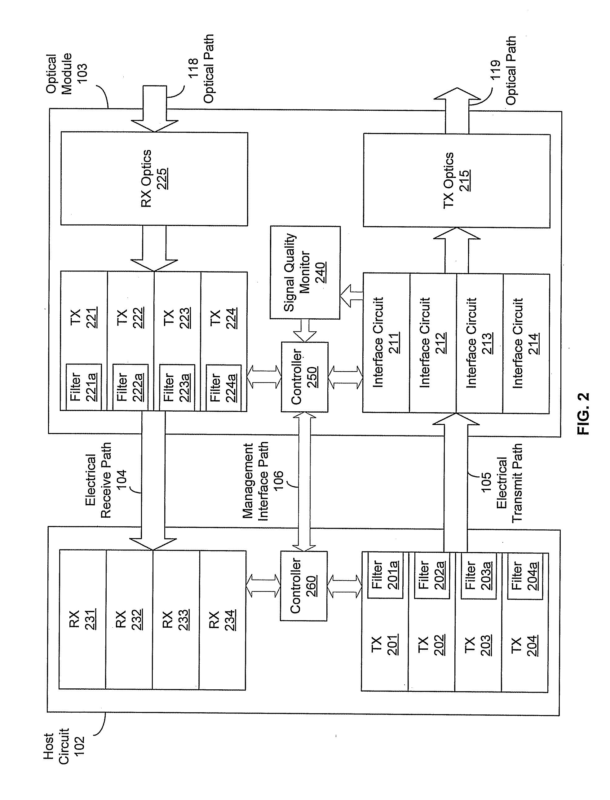
[0013]FIG. 2 is a block diagram illustrating an exemplary optical module architecture that is operable to adaptively set a transmitter filter for a high speed serial ...

Problems solved by technology

In the national networks, for example, dispersion may limit the transmission speeds between transmitters and receivers.
Optical dispersion is a fundamental problem for high-speed gigabit networks and is of particular importance as bit rates exceed 2.4 gigabits / sec, for example.
Intersymbol interference (ISI) may occur in digital communications in bandwidth-limited links.

Method used


Image

  • Method and System for Adaptively Setting a Transmitter Filter for a High Speed Serial Link Transmitter
  • Method and System for Adaptively Setting a Transmitter Filter for a High Speed Serial Link Transmitter
  • Method and System for Adaptively Setting a Transmitter Filter for a High Speed Serial Link Transmitter

Examples


Embodiment Construction

[0017]Certain embodiments of the invention can be found in a method and system for adaptively setting a transmitter filter for a high speed serial link transmitter. In various embodiments of the invention, a communication device, which may comprise a host circuit and an optical module, may be operable to determine, in the optical module, a signal quality associated with each of one or more host transmitter filters in the host circuit. The determined signal quality may be communicated from the optical module to the host circuit via a management interface. The communication device may be operable to control, in the host circuit, setting or configuration of each of the one or more host transmitter filters based on the determined signal quality. In this regard, the management interface may comprise, for example, a management data input / output (MDIO) interface and / or an inter-integrated circuit (I2C) interface. Each of the one or more host transmitter filters may comprise a pre-emphasis ...


PUM


Abstract

A communication device may be operable to determine, in an optical module, a signal quality associated with each of one or more host transmitter filters in a host circuit. The signal quality may be communicated from the optical module to the host circuit via a management interface. The communication device may control, in the host circuit, configuration of each of the host transmitter filters based on the signal quality. The communication device may be operable to determine, in the host circuit, a signal quality associated with each of one or more module transmitter filters in the optical module. The signal quality associated with each of the module transmitter filters may be communicated from the host circuit to the optical module via the management interface. The communication device may control, in the optical module, configuration of each of the module transmitter filters based on the signal quality.

Description

CROSS-REFERENCE TO RELATED APPLICATIONS / INCORPORATION BY REFERENCE[0001]This patent application makes reference to, claims priority to, and claims benefit from United States Provisional Application Ser. No. 61 / 322,185, which was filed on Apr. 8, 2010.[0002]This application also makes reference to:[0003]U.S. patent application Ser. No. 10 / 418,035 filed on Apr. 17, 2003, issued as U.S. Pat. No. 7,321,612 on Jan. 22, 2008; and[0004]U.S. patent application Ser. No. 11 / 268,246 filed on Nov. 7, 2005, issued as U.S. Pat. No. 7,676,158 on Mar. 9, 2010.[0005]Each of the above stated applications is hereby incorporated herein by reference in its entirety.FIELD OF THE INVENTION[0006]Certain embodiments of the invention relate to communication systems. More specifically, certain embodiments of the invention relate to a method and system for adaptively setting a transmitter filter for a high speed serial link transmitter.BACKGROUND OF THE INVENTION[0007]High speed fiber optical systems may be us...

Claims


Application Information

Patent Timeline
IPC IPC(8): H04B17/00
CPCH04B10/40H04B10/0799H04L25/03343
Inventor BHOJA, SUDEEPGHIASI, ALI
Owner AVAGO TECH INT SALES PTE LTD
Learn More